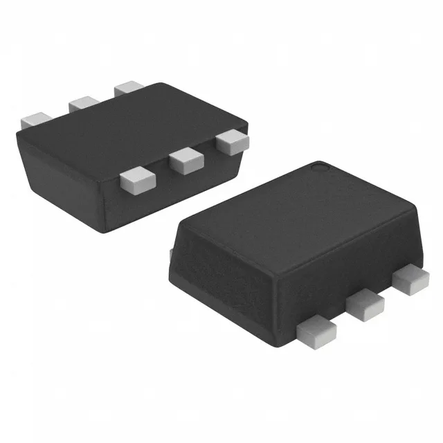
Toshiba Semiconductor RN4906FE,LF(CT — Discrete Semiconductors

Toshiba RN4906FE,LF(CT Dual NPN/PNP Pre-Biased Transistor

MPNRN4906FE,LF(CT
End of Life

Toshiba Semiconductor RN4906FE,LF(CT dual NPN/PNP pre-biased transistor, SOT-563 surface-mount, 100 mA collector, 50 V, 100 mW, built-in bias resistors 4.7k / 47k.

$0.27Ref. price · indicative, final on quote
PackagingSOT-563, SOT-666
StockIn Stock (20)
Lead timeIn Stock wk
MOQ1 pcs
  • 100% new & originalTraceable channels only — no refurbs, no pulls, no remarked parts.
  • Date & lot codes on quoteStated per line before you commit; label photos on request.
  • MSL-compliant ESD packingMoisture-sealed bags with indicator cards; reels photo-verified.
  • PayPal buyer protectionPay by T/T, PayPal or Payoneer — card payments covered end to end.

Specifications

RN4906FE,LF(CT Technical Specifications
ParameterValue
Mounting typeSurface Mount
FET type1 NPN, 1 PNP - Pre-Biased (Dual)
Voltage - collector emitter breakdown50V
Current - collector (Ic)100mA
Current - collector cutoff100nA (ICBO)
DC current gain (hFE) (Min) @ ic, vce80 @ 10mA, 5V
Power - max100mW
Frequency200MHz
PackageTape & Reel (TR); Cut Tape (CT)
CaseSOT-563, SOT-666
Resistor - base (R1)4.7kOhms
Resistor - emitter base (R2)47kOhms
Vce saturation (Max) @ ib, ic300mV @ 250µA, 5mA

Product details

The RN4906FE,LF(CT packs one NPN and one PNP pre-biased transistor into a single SOT-563 package, each with built-in bias resistors — R1 (base) at 4.7 kΩ and R2 (emitter-base) at 47 kΩ. That resistor network eliminates two external resistors per channel, saving board space and reducing pick-and-place count on high-density digital output or driver stages. The 100 mW power dissipation ceiling means the total heat from both junctions must stay under that limit; at 5 mA per channel the margin is comfortable, but running both channels near 100 mA simultaneously will exceed the package thermal budget. Minimum DC current gain of 80 at 10 mA collector current and 5 Vce means the base drive from a GPIO pin (typically 1-3 mA through the internal 4.7 kΩ resistor) is enough to saturate the output. The 300 mV Vce saturation at 250 µA base current and 5 mA collector confirms the transistor switches cleanly into saturation for low-side or high-side switching.

The surface-mount package suits automated assembly lines; the small size demands careful solder paste volume control to avoid bridging between the tight-pitch pins.

Active production and compliance

Listed as Active — current production from Toshiba Semiconductor. ROHS3 compliant, no exemptions noted.

Frequently asked questions

What is the difference between RN4906FE and RN4905FE?

The RN4905FE uses a 2.2 kΩ base resistor (R1) instead of the 4.7 kΩ on the RN4906FE. All other ratings — 100 mA collector, 50 V, 100 mW, SOT-563 package, 47 kΩ emitter-base resistor — are identical. The lower base resistance on the RN4905FE draws more current from the driving pin but saturates the output at a lower collector current.

Will RN4906FE drop into a board designed for RN4986FE?

Yes — the RN4986FE shares the same SOT-563 package, pinout, 4.7 kΩ / 47 kΩ bias resistor values, and 100 mA / 50 V ratings. The only difference is the RN4986FE has a 250 MHz transition frequency versus 200 MHz on the RN4906FE. For switching applications below 10 MHz the parts are functionally interchangeable.