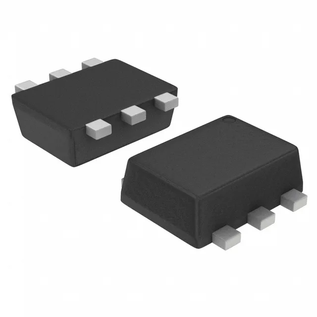
Toshiba Semiconductor RN2907,LF(CT — Discrete Semiconductors

Toshiba RN2907,LF(CT Dual PNP Pre-Biased, 10k/47k

MPNRN2907,LF(CT
End of Life

Toshiba Semiconductor RN2907 series dual PNP pre-biased transistor, 50 V, 100 mA, 200 mW, 10 kOhm base resistor, 47 kOhm base-emitter resistor, US6 surface-mount package, Tape & Reel.

$0.28Ref. price · indicative, final on quote
Packaging6-TSSOP, SC-88, SOT-363
StockIn Stock (20)
Lead timeIn Stock wk
MOQ1 pcs
  • 100% new & originalTraceable channels only — no refurbs, no pulls, no remarked parts.
  • Date & lot codes on quoteStated per line before you commit; label photos on request.
  • MSL-compliant ESD packingMoisture-sealed bags with indicator cards; reels photo-verified.
  • PayPal buyer protectionPay by T/T, PayPal or Payoneer — card payments covered end to end.

Specifications

RN2907,LF(CT Technical Specifications
ParameterValue
Mounting typeSurface Mount
FET type2 PNP - Pre-Biased (Dual)
Voltage - collector emitter breakdown50V
Current - collector (Ic)100mA
Current - collector cutoff500nA
DC current gain (hFE) (Min) @ ic, vce80 @ 10mA, 5V
Power - max200mW
Frequency200MHz
PackageTape & Reel (TR); Cut Tape (CT)
Case6-TSSOP, SC-88, SOT-363
Resistor - base (R1)10kOhms
Resistor - emitter base (R2)47kOhms
Vce saturation (Max) @ ib, ic300mV @ 250µA, 5mA

Product details

50 V, 100 mA continuous collector rating

The RN2907,LF(CT: Minimum DC current gain of 80 at 10 mA, 5 V ensures consistent switching performance across the batch; the 200 MHz transition frequency keeps switching losses negligible at typical PWM frequencies below 100 kHz. Power dissipation is limited to 200 mW total — in a 25 °C ambient the US6 package's thermal resistance means each transistor should stay below 100 mW continuous when both are on simultaneously, or the junction temperature climbs past the safe operating area.

What the 10 kOhm base resistor means for the BOM

The 10 kOhm R1 sets the base current when the drive voltage is applied — at 5 V logic, the base sees roughly (5 V - 0.7 V) / 10 kOhm ≈ 430 µA, which with a minimum hFE of 80 supports a collector current of about 34 mA, well within the 100 mA rating. The 47 kOhm R2 across base-emitter provides a guaranteed off-state: with the drive at 0 V, the resistor pulls the base to emitter, keeping collector cutoff below 500 nA — critical for preventing leakage-driven loads in battery-powered or high-impedance circuits.

Frequently asked questions

What is the difference between RN2907,LF(CT and RN2906,LF?

The RN2907 uses a 10 kOhm base resistor (R1), while the RN2906 uses a 4.7 kOhm R1. Both share the same 47 kOhm base-emitter resistor (R2), 50 V rating, 100 mA collector current, and US6 package. The higher R1 in the RN2907 draws less base current from the drive source, suiting it for lower-drive logic outputs.

What is the closest functional second-source to RN2907,LF(CT?

The RN2967(TE85L,F) is functionally equivalent — same dual PNP pre-biased topology, same 10 kOhm / 47 kOhm resistor divider, same 50 V / 100 mA ratings and US6 footprint. It drops into the same PCB pads without layout changes.

What compliance documentation does Toshiba provide for RN2907,LF(CT?

Toshiba certifies the RN2907,LF(CT as ROHS3 Compliant. Standard documentation includes the datasheet with electrical characteristics, package outline drawing, and the ROHS declaration of compliance.