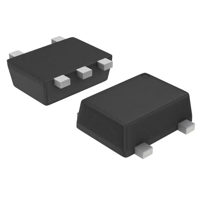
Toshiba Semiconductor RN2709JE(TE85L,F) — Discrete Semiconductors

Toshiba RN2709JE(TE85L,F) dual PNP pre-biased transistor

MPNRN2709JE(TE85L,F)
End of Life

Toshiba Semiconductor RN2709JE(TE85L,F) dual PNP pre-biased (emitter coupled) transistor, SOT-553 package, 100mW power dissipation, 50V Vce, 100mA Ic.

$0.46Ref. price · indicative, final on quote
PackagingSOT-553
StockIn Stock (30)
Lead timeIn Stock wk
MOQ1 pcs
  • 100% new & originalTraceable channels only — no refurbs, no pulls, no remarked parts.
  • Date & lot codes on quoteStated per line before you commit; label photos on request.
  • MSL-compliant ESD packingMoisture-sealed bags with indicator cards; reels photo-verified.
  • PayPal buyer protectionPay by T/T, PayPal or Payoneer — card payments covered end to end.

Specifications

RN2709JE(TE85L,F) Technical Specifications
ParameterValue
Mounting typeSurface Mount
FET type2 PNP - Pre-Biased (Dual) (Emitter Coupled)
Voltage - collector emitter breakdown50V
Current - collector (Ic)100mA
Current - collector cutoff100nA (ICBO)
DC current gain (hFE) (Min) @ ic, vce70 @ 10mA, 5V
Power - max100mW
Frequency200MHz
PackageTape & Reel (TR); Cut Tape (CT)
CaseSOT-553
Resistor - base (R1)47kOhms
Resistor - emitter base (R2)22kOhms
Vce saturation (Max) @ ib, ic300mV @ 250µA, 5mA

Product details

Dual PNP pre-biased transistor in SOT-553

The RN2709JE(TE85L,F) from Toshiba Semiconductor integrates two PNP transistors with built-in bias resistors in a single SOT-553 package — a space-saving option for switching and interface circuits where external resistor networks would otherwise consume board area. Each transistor is rated for 50 V collector-emitter breakdown and 100 mA continuous collector current, with a maximum power dissipation of 100 mW for the dual device.

Built-in bias resistors set the switching threshold

The base resistor (R1) is 47 kΩ and the base-emitter resistor (R2) is 22 kΩ — this divider network sets the turn-on threshold and provides a leakage path to ground, keeping the transistor off when the drive signal is absent. The 200 MHz transition frequency means the transistor can handle switching applications well into the low-MHz range, though the bias resistor network will limit the practical switching speed more than the fT itself.

Frequently asked questions

What is the closest functional alternative to the RN2709JE(TE85L,F)?

The RN2909FE(TE85L,F) is a close functional peer — same dual PNP pre-biased topology, same 47 kΩ / 22 kΩ resistor network, same 100 mA collector current and 50 V rating, but in a different package (SOT-553 vs the RN2909's package). The RN2713JE(TE85L,F) shares the same emitter-coupled dual PNP structure and SOT-553 package but uses a different bias resistor ratio (47 kΩ base resistor only, no base-emitter resistor).

What is the maximum power dissipation of the RN2709JE(TE85L,F)?

The RN2709JE(TE85L,F) is rated for 100 mW maximum power dissipation for the dual device in the SOT-553 package — this is the total for both transistors combined, so each transistor's dissipation must be derated accordingly in a balanced design.