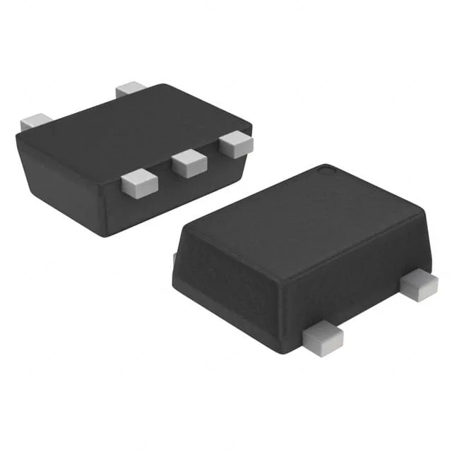
Toshiba Semiconductor RN2704JE(TE85L,F) — Memory (DRAM / SRAM / Flash / EEPROM)

Toshiba RN2704JE(TE85L,F) dual PNP pre-biased transistor

MPNRN2704JE(TE85L,F)
End of Life

Toshiba RN2704JE(TE85L,F) dual PNP pre-biased (emitter-coupled) transistor, 50 V collector-emitter breakdown, 100 mA collector current, 47kΩ base and emitter resistors, 200 MHz transition frequency, SOT-553 package, surface mount.

$0.49Ref. price · indicative, final on quote
PackagingSOT-553
RoHSRoHS Compliant
Sourced new & surplus through independent channelsAuthenticity-screened · ESD-safe packingListing updated Aug 2026

Specifications

RN2704JE(TE85L,F) specifications
ParameterValue
MountingSurface Mount
FET type2 PNP - Pre-Biased (Dual) (Emitter Coupled)
Voltage - collector emitter breakdown50V
Current - collector (Ic)100mA
Current - collector cutoff100nA (ICBO)
DC current gain (hFE) (Min) @ ic, vce80 @ 10mA, 5V
Power - max100mW
Frequency200MHz
PackageTape & Reel (TR); Cut Tape (CT)
CaseSOT-553
Resistor - base (R1)47kOhms
Resistor - emitter base (R2)47kOhms
Vce saturation (Max) @ ib, ic300mV @ 250µA, 5mA

Product details

Dual PNP pre-biased pair — two transistors, one SOT-553 package

The Toshiba RN2704JE(TE85L,F) packs two PNP transistors with built-in bias resistors into a single SOT-553 package. Each transistor has a 47kΩ resistor in series with the base and a 47kΩ resistor from base to emitter, so you get a complete switching stage without adding external resistors to the board. Collector-emitter breakdown is rated at 50 V, and each side handles up to 100 mA continuous collector current. The 200 MHz transition frequency means it keeps up with fast switching in signal-level applications.

47kΩ built-in resistors — two fewer parts per channel

With R1 and R2 both at 47kΩ, the RN2704JE forms a complete inverter or driver stage with just the transistor package and a load resistor. That matters when you are squeezing a multi-channel interface into a tight layout — the SOT-553 footprint plus the integrated resistors saves real estate versus four discretes. The pre-biased topology also guarantees the base-emitter resistor is always present, so leakage at high temperature stays controlled without a separate resistor on the board.

50 V, 100 mA — signal-level switching, not power

The 50 V VCEO and 100 mA IC maximums place this part firmly in the signal-switching and driver category. It is sized for relay and solenoid drivers, LED indicators, level shifters, and logic interface circuits where the load stays under 100 mA. The 300 mV saturation voltage at 250 µA base drive and 5 mA collector current is tight enough to keep dissipation low in a 100 mW maximum package. That 100 mW total is the package ceiling — split across both transistors, so derate if both sides run near their limits simultaneously.

Active, RoHS compliant — no LTB worry

No end-of-life notification, no last-time-buy pressure.

Frequently asked questions

What is the price of RN2704JE(TE85L,F) and where can I buy it?

Pricing and availability directly influence the sourcing decision for procurement buyers.

Is RN2704JE(TE85L,F) in stock at major distributors?

Stock availability determines lead time and urgency for BOM line fulfillment.

What are the exact specifications and datasheet for RN2704JE?

Design engineers need to validate fit for their circuit; datasheet is the primary reference.

What is the pinout diagram of RN2704JE(TE85L,F)?

Accurate pin configuration is critical for PCB layout and replacement by maintenance techs.

What is a suitable replacement or equivalent for RN2704JE?

Finding a drop-in replacement avoids redesign and ensures continuity during shortages or EOL.

Is the RN2704JE(TE85L,F) obsolete or end-of-life?

Lifecycle status impacts long-term availability and may force a last-time buy or alternative search.