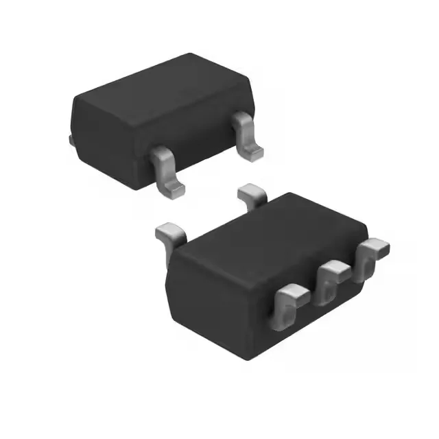
Dual PNP pre-biased in a small SOT-753
The Toshiba RN2503(TE85L,F) packs two PNP pre-biased transistors with emitter-coupled configuration into a single SC-74A (SOT-753) surface-mount package. Each transistor has 22kΩ base and emitter-base resistors built in, so you drop the two external bias resistors from the BOM — saves board space and placement cost on high-density designs. Rated for 50V collector-emitter breakdown and 100mA continuous collector current, with 300mW total power dissipation across both devices. The 200MHz transition frequency means it handles switching up into the low-MHz range — fine for gate drive, signal routing, or logic-level translation where you need a matched pair.
What the ratings mean on the bench
The 22kΩ base resistor (R1) and 22kΩ emitter-base resistor (R2) set the turn-on threshold and input impedance — with 5V on the base, the base current is about (5-0.7)/22k ≈ 195µA, which saturates the output at 5mA with only 300mV Vce(sat). That is a clean logic-level switch for driving a relay coil, LED string, or another transistor stage. Minimum DC current gain of 70 at 10mA, 5V means you get consistent gain across the operating range — the pre-biased resistors dominate the input characteristic, so batch-to-batch variation is tighter than a discrete resistor-transistor pair. The 100nA max collector cutoff keeps leakage negligible in off-state.
Housed in SC-74A (SOT-753), also designated SMV by Toshiba — a 5-pin surface-mount package with 0.95mm pitch. The small footprint fits tight layouts, and the emitter-coupled pair shares the common emitter pin, so the pinout is straightforward: the two collectors and two bases come out to separate pins, with the emitters tied together internally.