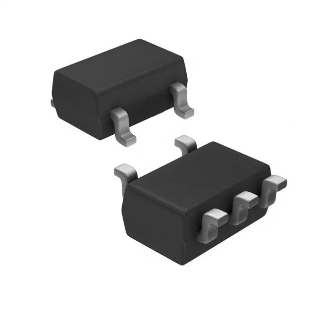
Dual PNP pre-biased in a single SC-74A
The RN2502(TE85L,F) integrates two PNP transistors with internal bias resistors — 10 kΩ base (R1) and 10 kΩ emitter-base (R2) — in an emitter-coupled pair, housed in a 5-pin SC-74A (SOT-753) SMV package. The built-in resistors eliminate the need for external base bias components, saving board space in high-density designs. Each transistor is rated for 50 V collector-emitter breakdown and 100 mA continuous collector current, with a maximum power dissipation of 300 mW for the dual device. The 200 MHz transition frequency supports switching applications up to low-MHz range.
Bias resistor ratio sets the switching threshold
With R1 = R2 = 10 kΩ, the input threshold voltage at the base is approximately half the supply voltage — the transistor turns on when the input exceeds Vbe(on) plus the voltage drop across R2. This symmetrical ratio is commonly used in inverter and logic-level interface circuits where a clean on/off transition is needed without external resistor dividers. The DC current gain is specified at a minimum of 50 at Ic = 10 mA, Vce = 5 V. Saturation voltage is 300 mV maximum at Ib = 250 µA, Ic = 5 mA — the internal resistors supply enough base drive to saturate the transistor at moderate collector currents.