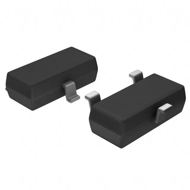
Toshiba Semiconductor RN2418,LF — Discrete Semiconductors

Toshiba RN2418,LF PNP Pre-Biased Transistor, 50V 100mA

MPNRN2418,LF
End of Life

Toshiba RN2418,LF PNP pre-biased transistor, 50 V collector-emitter breakdown, 100 mA collector current, 200 mW max power, SOT-23-3 S-Mini surface-mount package, Tape & Reel.

$0.17Ref. price · indicative, final on quote
PackagingTO-236-3, SC-59, SOT-23-3
StockContact for availability
Lead timeIn Stock wk
MOQ1 pcs
  • 100% new & originalTraceable channels only — no refurbs, no pulls, no remarked parts.
  • Date & lot codes on quoteStated per line before you commit; label photos on request.
  • MSL-compliant ESD packingMoisture-sealed bags with indicator cards; reels photo-verified.
  • PayPal buyer protectionPay by T/T, PayPal or Payoneer — card payments covered end to end.

Specifications

RN2418,LF Technical Specifications
ParameterValue
Mounting typeSurface Mount
FET typePNP - Pre-Biased
Voltage - collector emitter breakdown50 V
Current - collector (Ic)100 mA
Current - collector cutoff500nA
DC current gain (hFE) (Min) @ ic, vce50 @ 10mA, 5V
Power - max200 mW
Frequency200 MHz
PackageTape & Reel (TR); Cut Tape (CT)
CaseTO-236-3, SC-59, SOT-23-3
Resistor - base (R1)47 kOhms
Resistor - emitter base (R2)10 kOhms
Vce saturation (Max) @ ib, ic300mV @ 250µA, 5mA

Product details

Pre-biased PNP with integrated 47 kΩ / 10 kΩ divider

The RN2418,LF: Rated for 50 V collector-emitter breakdown and 100 mA continuous collector current, with a maximum power dissipation of 200 mW. The 200 MHz transition frequency supports moderate-speed switching — adequate for driving small relays, LEDs, or as a level translator up to a few hundred kilohertz.

Saturation and gain at the operating point

Vce saturation is specified at 300 mV max with a 250 µA base drive and 5 mA collector load — a 50:1 overdrive ratio that keeps the transistor firmly in saturation. Collector cutoff current is 500 nA max — low enough that the transistor does not leak into the load when the input is pulled high (off state). This matters for battery-powered circuits where off-state leakage directly drains the cell.

Package, compliance, and sourcing

The footprint is identical to generic SOT-23 small-signal transistors, so no board layout change is needed when substituting into an existing PNP pre-biased position.

Frequently asked questions

What is the closest functional second-source to RN2418,LF?

The RN2413TE85LF is a same-family peer with identical 47 kOhm base resistor, 50 V Vceo, 100 mA Ic, and 200 mW rating in the same SOT-23-3 package. The only difference is the emitter-base resistor: the RN2413 has no R2 (open), while the RN2418,LF integrates a 10 kOhm R2. For circuits that rely on the internal divider to pull the base low when the input is open, the RN2418,LF is the correct fit. The RN2416,LF (4.7 kOhm R1) and RN2412TE85LF (22 kOhm R1) are parametric alternatives but change the input threshold.

Will RN2418,LF drop into a board originally specified for RN2413TE85LF?

The two parts share the same SOT-23-3 footprint, voltage, current, and power ratings, so the board layout is compatible. The functional difference is the integrated 10 kOhm emitter-base resistor (R2) in the RN2418,LF, which pulls the base low when the input is open or high-impedance — the RN2413 has no internal R2. If the original circuit relied on an external pull-down or the input driver already holds the base low, the RN2418,LF works without rewiring. If the input is left floating, the RN2418,LF's internal R2 keeps the transistor off, which is usually the safer behavior.