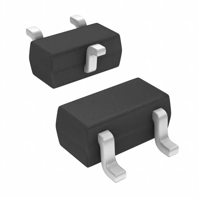
PNP pre-biased transistor, 50 V / 100 mA
The RN2104,LF(CT: The 100 mW power dissipation limit means the junction temperature stays within the package rating only when the collector current and Vce(sat) product stays under that ceiling; at 50 V and 5 mA the margin is comfortable, but at 100 mA and 300 mV saturation the dissipation is 30 mW, well inside the limit.
Built-in bias resistors simplify BOM
Both the base resistor (R1) and the emitter-base resistor (R2) are 47 kOhms, integrated into the same die — this eliminates two external passives per transistor and shrinks the placement area. The 47 kOhm / 47 kOhm divider sets the base drive for a given input voltage; with a 5 V logic signal the base current is roughly (5 V - 0.7 V) / 47 kOhm ≈ 91 µA, enough to saturate the transistor at collector currents up to about 7 mA given the minimum hFE of 80 at 10 mA / 5 V. Saturation voltage is specified at 300 mV maximum with a base drive of 250 µA and collector current of 5 mA — this is the on-state voltage drop across the collector-emitter junction when the transistor is fully turned on. For a 5 mA load the dissipation in saturation is 1.5 mW, negligible in the SC-75 package.
SC-75 SOT-416 — small footprint for dense boards
Housed in the SC-75 (SOT-416) surface-mount package, the RN2104,LF(CT occupies roughly 1.6 mm × 0.8 mm of board area — suitable for space-constrained designs in portable electronics, sensor modules, or I/O expansion where a single transistor replaces a discrete resistor pair. The supplier device package is designated SSM, a Toshiba-specific code for the SC-75 outline. CT suits prototyping or low-volume builds where partial reels are acceptable.
Active production — RoHS3 compliant
For new designs the part is a direct fit; for existing BOM lines it can be sourced to order against the required quantity, with availability confirmed at quote time.