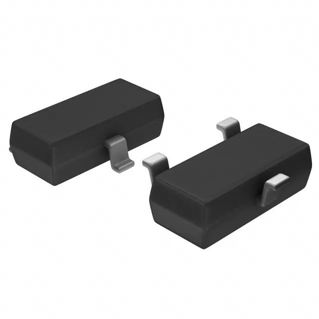
Bias resistor network sets the on/off threshold
The RN1403,LF integrates a 22 kOhm base resistor (R1) and a 22 kOhm emitter-base resistor (R2) — a 1:1 divider that defines the input voltage at which the transistor turns on. With both resistors equal, the switch-on threshold sits at roughly half the drive voltage, so a 5 V logic signal needs to exceed about 2.5 V at the base pin to saturate the output. This fixed ratio eliminates the external bias resistor pair, saving one component per channel on the board.
50 V breakdown and 100 mA continuous collector current
Rated for 50 V collector-emitter breakdown and 100 mA continuous collector current, this pre-biased NPN handles typical low-side switching of relay coils, indicator LEDs, or small solenoid valves in 24 V industrial logic circuits. The 200 mW power dissipation limit in the SOT-23-3 package means the actual continuous current at elevated ambient temperature is lower than the 100 mA headline — at 85 °C ambient the derating curve typically halves the allowable dissipation, so a 50 mA load is a safer continuous target without exceeding the junction temperature.
250 MHz transition frequency and saturation voltage
With a 250 MHz transition frequency, the RN1403,LF switches fast enough for PWM dimming of LEDs at tens of kilohertz or for driving the base of a larger power transistor in a Darlington pair. The minimum DC current gain of 70 at 10 mA collector current ensures the base drive from a microcontroller GPIO (typically 2-5 mA) saturates the output reliably.