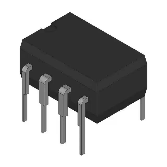
Dual 4A gate driver in an 8-pin DIP — what the 20 ns rise time buys you
That rise/fall pair sets the minimum achievable dead-time and the switching loss floor for the power stage — a driver that cannot slew the gate fast enough forces the designer to extend dead-time, which eats into the duty-cycle window and increases conduction loss in the body diode. Each channel is independent with both inverting and non-inverting inputs, so one part handles complementary drive signals or two independent gate drives without external logic.
Through-hole PDIP — why it still makes sense on a power board
On a power board with a 2 oz copper plane and a TO-220 MOSFET, the PDIP footprint lets you route the gate loop on the top layer with a short, wide trace from pin to gate resistor — no via stub, no inductance from a socket. The tube shipment is typical for DIP parts; the package is not moisture-sensitive, so no bake required before hand-assembly or rework. That covers industrial motor drives, outdoor telecom rectifiers, and under-hood automotive auxiliary converters. The 125°C ceiling is the junction limit for the driver itself — the actual thermal headroom depends on the switching frequency and the gate charge of the driven MOSFET, not just the ambient number.
The part is a current-production line item at Texas Instruments, available through the independent distribution channel against an RFQ.