Half-bridge gate drive with matched edges
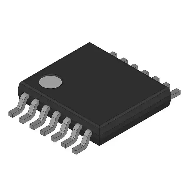
The UCC27222PWPR is a dual-channel, non-inverting, synchronous half-bridge gate driver from Texas Instruments, designed to drive two N-channel MOSFETs in a high-side/low-side configuration. Each channel delivers a peak output current of 4A source and 4A sink, enough to charge and discharge the gate capacitance of medium-power MOSFETs without lingering in the Miller plateau. Rise and fall times are both 17 ns typical — matching the edges within a few nanoseconds means the high-side and low-side gates transition with near-identical timing, which directly reduces the risk of cross-conduction (shoot-through) during the dead-time window. The supply voltage range spans 3.7V to 20V, letting it run from a 5V or 12V bias rail. The logic input thresholds — VIL at 0.7V, VIH at 2.6V — are compatible with 3.3V and 5V PWM controllers without external level shifters.
Package, temperature grade, and sourcing
What the 4A peak rating means in a real bridge
A 4A peak gate drive can charge a 10 nC gate (typical for a 60V, 30A MOSFET) in roughly 2.5 ns, though the actual switching speed is limited by the gate loop inductance and the driver's output resistance, not just the peak current number. The 17 ns rise/fall time in the datasheet is measured with a specified load — your actual edge rate depends on the total gate charge and the external gate resistor you add to control ringing. Because both channels are on the same die and share the same bias rail, the propagation delay mismatch between the high-side and low-side outputs is typically under 2 ns — this is the spec that matters for dead-time calculation. A mismatch of even 10 ns can eat into a 50 ns programmed dead-time and cause partial shoot-through.