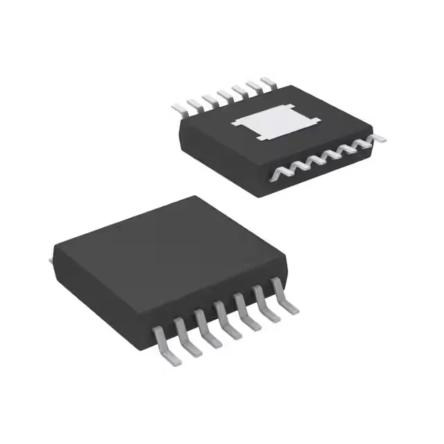
Half-bridge gate driver with 4A peak drive for synchronous N-channel MOSFETs
The supply voltage range spans 3.7V to 20V, covering common 5V, 12V, and 24V bias rails. The inverting input logic means the driver output is the complement of the input signal — useful when the PWM controller output polarity needs flipping to match the high-side / low-side timing.
What the 4A peak drive and 17ns edges mean for your switching stage
A 4A peak gate drive and 17ns rise/fall time set the minimum dead-time needed to avoid cross-conduction. The synchronous channel type provides break-before-make timing internally. The 14-HTSSOP package with exposed pad pulls heat from the driver die into the PCB copper. The junction temperature rating is -55°C to 115°C.
Obsolete — sourcing the UCC27221PWPR for existing BOM lines
Because the base product number is UCC272, there may be other variants in the family (different package, temperature grade, or tape/reel option) that are still active. A cross-reference search against the full UCC272xx family is worthwhile if the board can accommodate a different package or temperature range.