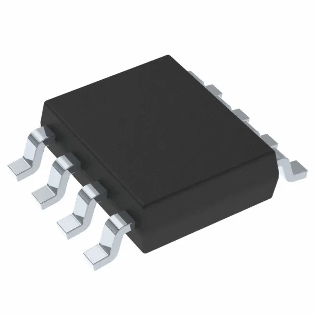
4A peak gate drive — what it buys you
The UCC27210DDA is a half-bridge gate driver from TI designed to drive two N-channel MOSFETs in an independent-channel configuration. Its headline rating is the 4 A peak source and 4 A peak sink current, which means it can charge and discharge the gate capacitance of medium-power MOSFETs quickly enough to keep switching losses under control in a 100–500 kHz converter. The 7.2 ns typical rise time and 5.5 ns fall time at the output let the designer budget a short dead-time between the high-side and low-side transitions without risking shoot-through — a common pain point when the driver edges are slower than the controller expects.
120 V bootstrap — the DC bus ceiling
The high-side bootstrap supply is rated to 120 V maximum, which sets the hard limit on the half-bridge DC bus voltage. For a 48 V or 72 V nominal bus this leaves comfortable margin; for a 100 V+ bus the designer must check the bootstrap diode voltage rating and the bootstrap capacitor charging time against the minimum on-time. The supply range is 8 V to 17 V, so the low-side bias rail is compatible with standard 12 V bias rails common in industrial and telecom power supplies. The logic input thresholds are 2.4 V (VIL) and 5.9 V (VIH), which means a 3.3 V PWM controller output will not reliably drive the input high — a level-shift buffer or a 5 V logic interface is needed.
140°C junction — thermal headroom for tight layouts
The operating junction temperature range extends from -40°C to 140°C, which is 15°C higher than the typical industrial 125°C limit. This extra headroom matters when the driver sits close to a hot inductor or a heatsink-mounted MOSFET in a sealed enclosure, or when the ambient temperature in a motor-drive cabinet hits 85°C and the self-heating from 4 A gate-drive pulses adds another 30–40°C.
8-PowerSOIC — rework and footprint notes
Without that, the 4 A gate-drive current at high frequency will push the junction past the 140°C ceiling. The tube shipment means the parts arrive with the leads protected, but the tube is not moisture-barrier — check the MSL label on the reel if you are reeling for production.