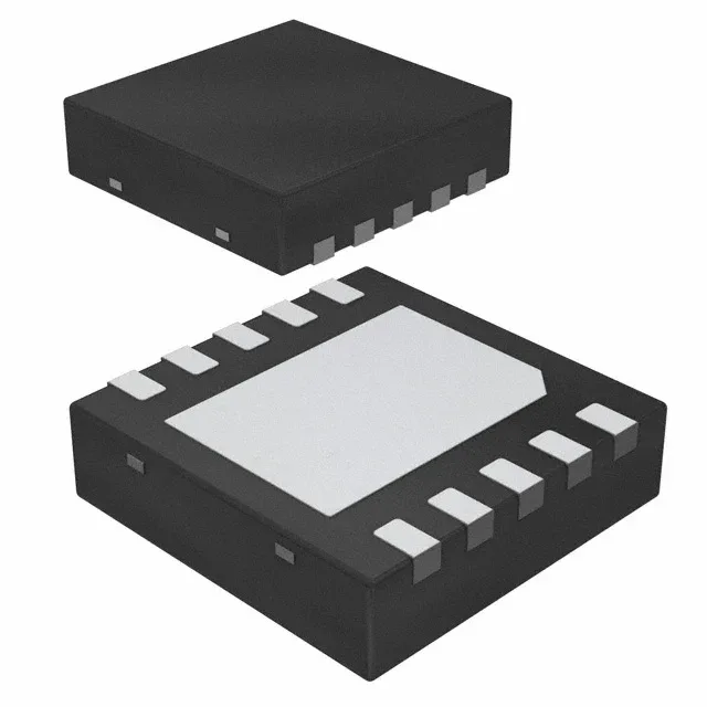
Texas Instruments UCC27201ADPRR — Power Management (PMIC / Gate Driver)

UCC27201ADPRR Gate Driver, 3A, 8V-17V, Half-Bridge, Active

MPNUCC27201ADPRR
Active

Texas Instruments UCC27201ADPRR, half-bridge N-channel MOSFET gate driver, 3A peak source/sink, 8V to 17V supply, 120V bootstrap, 8ns/7ns rise/fall, 10-WSON (4x4) surface mount, -40°C to 140°C junction.

$1.4700Ref. price · indicative, final on quote
Independent supplier — new & surplus stockAuthenticity-screened · ESD-safe packingListing updated Jul 2026

Specifications

UCC27201ADPRR specifications
ParameterValue
Gate typeN-Channel MOSFET
Input typeNon-Inverting
Channel typeIndependent
MountingSurface Mount
Supply voltage8V ~ 17V
Logic voltage - VIL, VIH0.8V, 2.5V
High side voltage - max (Bootstrap)120 V
Current - peak output (Source, sink)3A, 3A
Operating temperature-40°C~140°C(TJ)
PackageTape & Reel (TR); Cut Tape (CT)
Case10-WDFN Exposed Pad
Number of drivers2
Driven configurationHalf-Bridge
Rise (Fall time)8ns, 7ns

Product details

Half-bridge driver for 48V to 100V bus rails

The UCC27201ADPRR is a Texas Instruments half-bridge gate driver designed to drive two N-channel MOSFETs in a high-side/low-side configuration. Its 8V to 17V supply range covers standard 12V bias rails, and the 120V bootstrap rating handles 48V, 72V, and 100V DC bus systems common in motor drives, DC-DC converters, and UPS inverters. Peak output current of 3A source and 3A sink, combined with 8ns rise and 7ns fall times, charges and discharges the MOSFET gate capacitance quickly, reducing switching losses and cross-conduction in the half-bridge leg.

Supply rail and logic-level compatibility

The driver operates from a single 8V to 17V supply — a 12V rail sits comfortably in the middle. Logic inputs accept 0.8V VIL and 2.5V VIH thresholds, so a 3.3V or 5V microcontroller can drive the inputs directly without level shifting. Both channels are independent and non-inverting, meaning each input controls its respective output without inversion or cross-coupling. This simplifies firmware: a PWM timer output connects straight to the high-side input, another to the low-side input, and dead-time is handled in software or an external dead-time generator.

Thermal and package constraints for the layout

The -40°C to 140°C junction rating covers industrial motor-drive environments and under-hood automotive applications — the 140°C ceiling gives headroom above the typical 125°C ambient limit. Surface-mount assembly with the exposed pad means the PCB layout must include thermal vias under the pad to a copper plane.

Frequently asked questions

Is the UCC27201ADPRR obsolete or still active?

No discontinuation notice or last-time-buy date has been issued.

Does the UCC27201ADPRR work with a 12V supply?

Yes. The supply voltage range is 8V to 17V, so a 12V bias rail is within the operating window.

Can the UCC27201ADPRR drive two independent MOSFETs?

Yes. The two channels are independent and non-inverting, so each channel drives its own MOSFET without cross-coupling. The driven configuration is half-bridge, meaning one channel drives the high-side MOSFET and the other drives the low-side.