Texas Instruments TPS55289RYQR — Analog & Data Acquisition

TPS55289RYQR Buck-Boost Regulator, 6.35 A, 21-VQFN

MPNTPS55289RYQR
End of Life

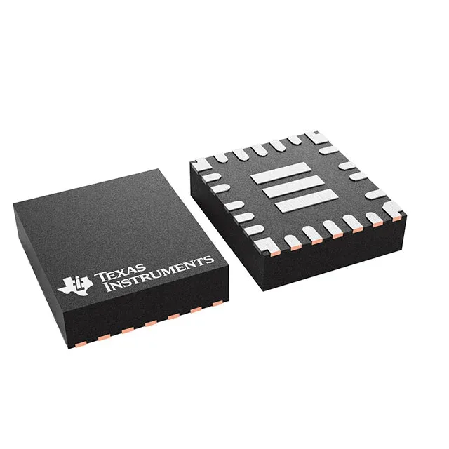
Texas Instruments TPS55289RYQR, adjustable buck-boost switching regulator, 6.35 A switch, 3 V to 30 V input, 200 kHz to 2.2 MHz, synchronous rectification, -40°C to 125°C, 21-PowerVFQFN.

$8.05Ref. price · indicative, final on quote
Packaging21-PowerVFQFN
StockContact for availability
MOQ1 pcs
  • 100% new & originalTraceable channels only — no refurbs, no pulls, no remarked parts.
  • Date & lot codes on quoteStated per line before you commit; label photos on request.
  • MSL-compliant ESD packingMoisture-sealed bags with indicator cards; reels photo-verified.
  • PayPal buyer protectionPay by T/T, PayPal or Payoneer — card payments covered end to end.

Specifications

TPS55289RYQR Technical Specifications
ParameterValue
Output typeAdjustable
Mounting typeSurface Mount
Voltage - input30V
Voltage - output0.8V
Voltage - output (Min (Fixed))0.8V
Current - output6.35A (Switch)
Frequency200kHz ~ 2.2MHz
Number of outputs1
Operating temperature-40°C ~ 125°C (TJ)
PackageTape & Reel (TR); Cut Tape (CT)
FunctionStep-Up/Step-Down
TopologyBuck-Boost
Case21-PowerVFQFN
Output configurationPositive
Synchronous rectifierYes

Product details

The TPS55289RYQR: Input voltage range is 3 V to 30 V. Output adjustable down to 0.8 V with synchronous rectification. Switching frequency programmable from 200 kHz to 2.2 MHz.

21-VQFN-HR (3x5) — footprint and thermal reality

The TPS55289RYQR is supplied in a 21-PowerVFQFN package, supplier device package 21-VQFN-HR measuring 3 mm x 5 mm. That is a compact land pattern for a 6.35 A switch, so the thermal pad and the via stitch under the package are not optional — they are part of the rated dissipation path. If you are hand-prototyping, the Cut Tape variant is the one to order.

Frequently asked questions

What is the output current of TPS55289RYQR?

The TPS55289RYQR is rated for 6.35 A on the internal switch. That is the switch current limit, not the continuous output current — the actual output current depends on the input-to-output voltage ratio, the inductor value, and the thermal design. For a typical 12 V input to 5 V output conversion, expect several amps continuous with adequate PCB copper.