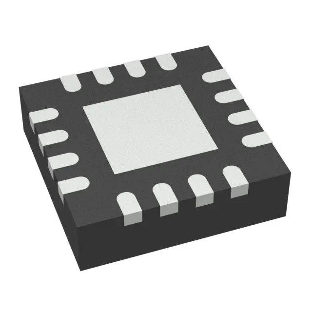
Flyback topology in a 3x3 mm QFN — what it means for the board
The TPS55010RTET is a single-output flyback regulator from Texas Instruments that handles step-up/step-down conversion with isolation capability. It takes a 2.98 V to 6 V input rail and delivers an adjustable output up to 20 V — the flyback transformer turns ratio sets the actual output, not the IC alone.
Switching frequency range and the inductor trade-off
The oscillator runs from 100 kHz to 2 MHz, set by a single resistor. At 2 MHz the flyback transformer shrinks to a few microhenries — good for board space — but the AC losses in the core and the switching losses in the FET rise. At 100 kHz the magnetics are larger but the efficiency peaks, especially under heavy load. The RT pin resistor value selects the frequency; no external clock sync is available. Synchronous rectification is built in — the internal low-side FET replaces the usual output diode, recovering the diode forward drop. This matters most at low output voltages where the diode drop is a large fraction of the rail; at 3.3 V out the efficiency gain over a diode flyback is typically 5-8%.
Output polarity and isolation — one IC, two configurations
The output configuration is listed as positive or negative, isolation capable. In a non-isolated flyback the output shares the input ground and the IC regulates a positive or negative rail. With a coupled inductor or transformer that has primary-to-secondary isolation, the output floats relative to input ground — the feedback path then crosses the isolation barrier, typically through an optocoupler or a transformer winding. The adjustable output starts from a 3.3 V minimum fixed reference (the internal error amplifier compares FB to 3.3 V). Below that voltage the part cannot regulate — the output must be higher than the reference. For rails under 3.3 V, an external divider from the output to FB still works because the FB pin is the error amp input, but the minimum achievable output is set by the internal reference.