Dual-output synchronous buck controller — what it does on the board
The TPS51120RHBR is a dual-output synchronous buck controller from TI's D-CAP™ series, designed to regulate two independent positive voltage rails from a single input supply. It drives external N-channel MOSFETs in a step-down (buck) topology, with synchronous rectification built into the control scheme — no external catch diode needed. Input voltage range spans 4.5V to 28V, covering standard 5V, 12V, and 24V intermediate buses found in industrial and computing power trees. The two outputs share one controller but regulate independently — useful for powering separate logic and I/O rails from the same upstream supply. That covers most factory-floor, telecom, and base-station environments without needing a wider-temp part.
Package and rework considerations — 32-VQFN with exposed pad
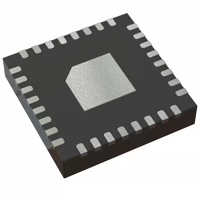
Housed in a 32-VFQFN with exposed pad, the TPS51120RHBR measures 5x5 mm (supplier device package 32-VQFN). Without it, the junction temperature rises fast under load. This is a surface-mount part, not socketed. If you are reworking a board in the field, you will need hot air or a reflow station — the QFN package does not lend itself to a soldering iron swap. The pad underneath is not visible, so alignment during rework takes a steady hand and a stencil or tacky flux. Cut Tape works for prototype or low-volume builds where you do not want a full reel.
Control features and what they mean for the BOM
The controller includes Enable, Power Good, and On Time Control. Enable lets a supervisor or sequencer gate the outputs; Power Good feeds back to a CPLD or reset generator so the downstream loads do not power up until both rails are within regulation. On Time Control is a constant-on-time scheme — no external compensation network. That simplifies the BOM by removing the RC loop filter, but it also means the switching frequency varies with input voltage. At higher VIN the on-time shortens and frequency rises; at lower VIN the opposite happens. The inductor and output cap must be sized for the worst-case frequency, not the nominal. No clock sync input — the controller free-runs. If the system has a sensitive ADC or RF section that needs a fixed switching frequency to avoid beat tones, this part may inject spurs that vary with line voltage. A synchronizable controller would be a better fit for that scenario.
RoHS3 compliant — no exemptions expiring soon.