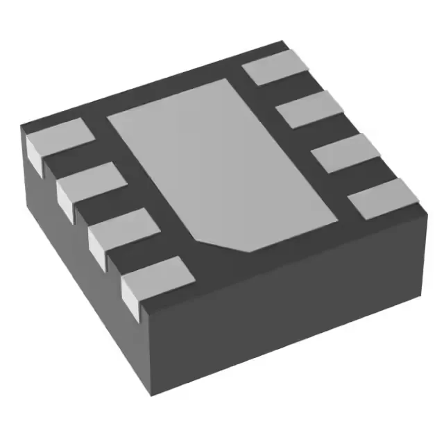
What the TPS259520DSGR does — and who needs it
The TPS259520DSGR is a Texas Instruments electronic fuse — a single-chip current-limiting and overvoltage protector for power rails that need a fast, resettable alternative to a discrete fuse or PTC. It sits between the supply and the load, and when the current exceeds the programmed threshold, it limits the output rather than blowing open. The input range spans 2.7V to 18V, and the device can deliver up to 4A continuous to the load. The 8-WSON (2x2 mm) package keeps the footprint small enough for space-constrained designs like USB-C power delivery ports or point-of-load protection on a multi-rail board.
Current-limit accuracy — why ±7.5% matters
The TPS259520DSGR specifies a ±7.5% accuracy on the current-limit threshold. That means if you set the limit at 3 A, the actual trip point falls between 2.775 A and 3.225 A across temperature and process. For a 4 A rail feeding a motor or a bank of capacitors, that guard band keeps you from nuisance-tripping on inrush while still protecting the downstream components. A wider-tolerance part would force you to set the limit lower, reducing the usable load current.
Package and thermal — 8-WSON with exposed pad
For a 4 A pass element, the copper area under the pad sets the junction-to-ambient thermal resistance — a solid via array to an inner-layer ground plane is the standard approach. The 2x2 mm body means the fan-out vias sit tight; the layout engineer should plan for at least four thermal vias directly under the pad.