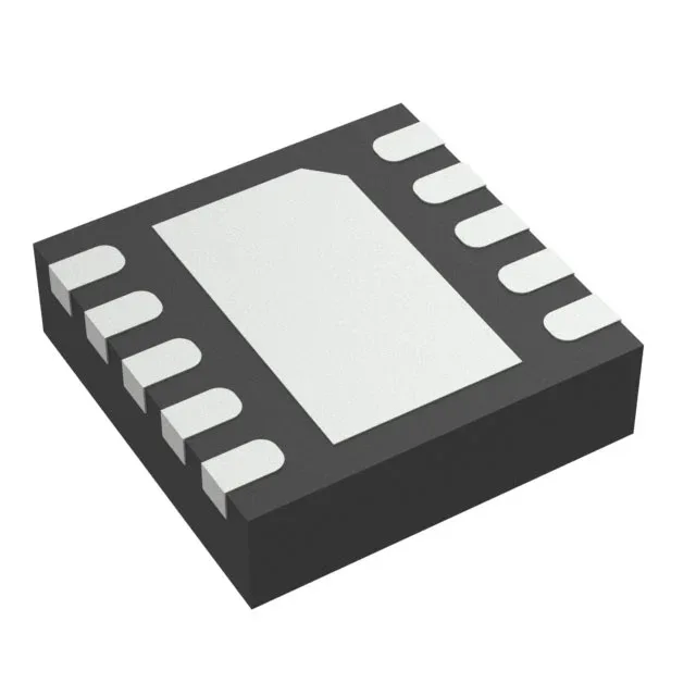
Texas Instruments TPS2561ADRCT — Power Management (PMIC / Gate Driver)

TPS2561ADRCT Texas Instruments Power Switch – 2.5 A, 44 mOhm

MPNTPS2561ADRCT
Active

Texas Instruments TPS2561ADRCT, dual-channel high-side power switch, 2.5 V to 6.5 V load, 44 mOhm typical Rds(on), 2.5 A max per output, adjustable current limiting, over-temperature and UVLO protection, 10-VSON (3x3 mm) package, -40°C to 125°C junction temperature.

$1.6800Ref. price · indicative, final on quote
Packaging10-VFDFN Exposed Pad
RoHSROHS3 Compliant
Independent supplier — new & surplus stockAuthenticity-screened · ESD-safe packingListing updated Aug 2026

Specifications

TPS2561ADRCT specifications
ParameterValue
Input typeNon-Inverting
Output typeN-Channel
TypeGeneral Purpose
MountingSurface Mount
Voltage - load2.5V ~ 6.5V
Voltage - supply (Vcc (Vdd))Not Required
Output current2.5A
I/O channels2
InterfaceOn/Off
Operating temperature-40°C~125°C(TJ)
PackageTape & Reel (TR); Cut Tape (CT)
FeaturesSlew Rate Controlled, Status Flag
Rds on44mOhm
Case10-VFDFN Exposed Pad
Fault protectionCurrent Limiting (Adjustable), Over Temperature, UVLO
Output configurationHigh Side
Ratio - Input:Output1:2

Product details

Dual high-side switch with adjustable current limit

The TPS2561ADRCT is a dual-channel high-side power switch from Texas Instruments, designed to distribute power to USB ports, peripheral loads, and general-purpose 2.5 V to 6.5 V rails. Each of the two N-channel outputs delivers up to 2.5 A continuous, with a typical on-resistance of 44 mOhm — the conduction loss at 2.5 A is roughly 275 mW per channel, which the 10-VSON exposed pad must sink to the board. The switch is self-contained: no external Vcc supply is needed, and the On/Off interface accepts a non-inverting logic signal. The slew-rate controlled turn-on limits inrush current, and the open-drain status flag reports overcurrent or thermal fault conditions.

Parametric fit: Rds(on), input range, and protection

The 44 mOhm typical Rds(on) at 2.5 A sets a voltage drop of roughly 110 mV per channel — low enough to keep a 5 V USB rail above the 4.75 V minimum under full load. The load voltage range of 2.5 V to 6.5 V covers 3.3 V and 5 V rails, and the device does not require a separate bias supply. Fault protection includes adjustable current limiting (set with an external resistor), over-temperature shutdown, and undervoltage lockout. The 1:2 input-to-output ratio means a single enable signal gates both channels simultaneously — useful for ganged power domains.

Package, temperature grade, and sourcing posture

The 10-VSON package (3x3 mm, 0.50 mm pitch) with exposed pad requires a thermal land on the PCB — the datasheet recommends a 2.8x2.8 mm pad with at least four thermal vias to the ground plane.

Frequently asked questions

How can I order TPS2561ADRCT or request a quote?

TPS2561ADRCT is active and ROHS3 compliant. We source it to order against your BOM quantity — submit an RFQ through the site for current pricing and lead time. Tape & Reel and Cut Tape options are available from the factory.

What is the Rds(on) and input voltage range of TPS2561ADRCT?

Typical Rds(on) is 44 mOhm per channel. The load voltage range is 2.5 V to 6.5 V, covering 3.3 V and 5 V rails. No separate Vcc supply is needed.

What package does TPS2561ADRCT come in?

It is offered in a 10-VFDFN exposed pad package (10-VSON, 3x3 mm body). The supplier device package is 10-VSON (3x3). Mounting is surface mount.