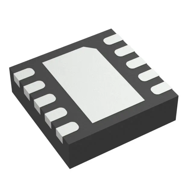
Texas Instruments TPS2555DRCR — Power Management (PMIC / Gate Driver)

TPS2555DRCR Texas Instruments Power Switch, 2.5 A, 73 mOhm

MPNTPS2555DRCR
Active

Texas Instruments TPS2555DRCR, high-side power switch, 1 output, N-channel, 4.5 V to 5.5 V load, 2.5 A max, 73 mOhm Rds(on), adjustable current limit, status flag, -40°C to 125°C, 10-VSON (3x3) package, Tape & Reel.

$0.9900Ref. price · indicative, final on quote
Independent supplier — new & surplus stockAuthenticity-screened · ESD-safe packingListing updated Jul 2026

Specifications

TPS2555DRCR specifications
ParameterValue
Output typeN-Channel
TypeGeneral Purpose
MountingSurface Mount
Voltage - load4.5V ~ 5.5V
Voltage - supply (Vcc (Vdd))Not Required
Output current2.5A
I/O channels1
InterfaceOn/Off
Operating temperature-40°C~125°C(TJ)
PackageTape & Reel (TR)
FeaturesStatus Flag
Rds on73mOhm
Case10-VFDFN Exposed Pad
Fault protectionCurrent Limiting (Adjustable), Over Temperature, UVLO
Output configurationHigh Side
Ratio - Input:Output1:1

Product details

2.5 A high-side switch with adjustable current limit

The 73 mOhm typical Rds(on) keeps voltage drop under 200 mV at full load, which matters for USB VBUS distribution where the downstream device sees the switch's dropout. The adjustable current limit lets you set the trip point with a single external resistor, so the same PCB layout can serve 0.5 A, 1 A, or 2.5 A ports by changing one resistor value.

Fault protection and status reporting

Three protection circuits are integrated: adjustable current limiting, over-temperature shutdown, and under-voltage lockout (UVLO). The open-drain Status Flag output asserts low when the switch is in current-limit or thermal-shutdown — a direct feed to a GPIO for system-level fault logging or load disconnect. No external comparator or supervisor needed.

Frequently asked questions

What is the TPS2555DRCR current limit range?

The current limit is adjustable via an external resistor. The device is rated for a maximum continuous output of 2.5 A. The exact current limit range depends on the resistor value selected; the datasheet provides the ILIMIT vs RLIMIT curve for setting the trip point.