PCMCIA slot power — one chip, three rails
The TPS2226ADBRG4 from Texas Instruments is a quad high-side PCMCIA power switch that delivers 1 A per channel across the three voltage rails a PC Card or CardBus slot needs: 3.3 V, 5 V, and 12 V. It integrates four independent output switches with a 3:4 input-to-output ratio, meaning the three supply inputs are selectively routed to four output pins — the arrangement that drives two PCMCIA sockets from one controller. The serial interface handles the Vpp and Vcc switching commands from the host PCMCIA controller, and the Status Flag output reports fault conditions back to the system without extra GPIO.
95 mOhm Rds(on) — the conduction loss number
At 95 mOhm typical on-resistance, each channel drops under 95 mV at the full 1 A load. That voltage loss subtracts directly from the card's supply rail, so the upstream regulator must compensate by setting its output 95 mV higher than the card's minimum operating voltage. The 95 mOhm figure is the typical value at 25 °C; junction temperature rise will increase it per the normalised Rds(on) curve in the datasheet, so the thermal design should budget for the hot-case resistance when the switch is running near its 1 A ceiling.
Fault protection without a supervisor
Fixed current limiting and over-temperature shutdown are built in — no external sense resistor or comparator needed. When a shorted card or a stalled 12 V programming pulse pulls the output current above the limit threshold, the switch clamps the current and the Status Flag asserts low. If the die temperature exceeds the thermal shutdown threshold, the switch latches off until it cools. This self-protection means the PCMCIA slot can survive a card fault without blowing the PCB trace or the upstream regulator.
30-SSOP package — footprint and layout
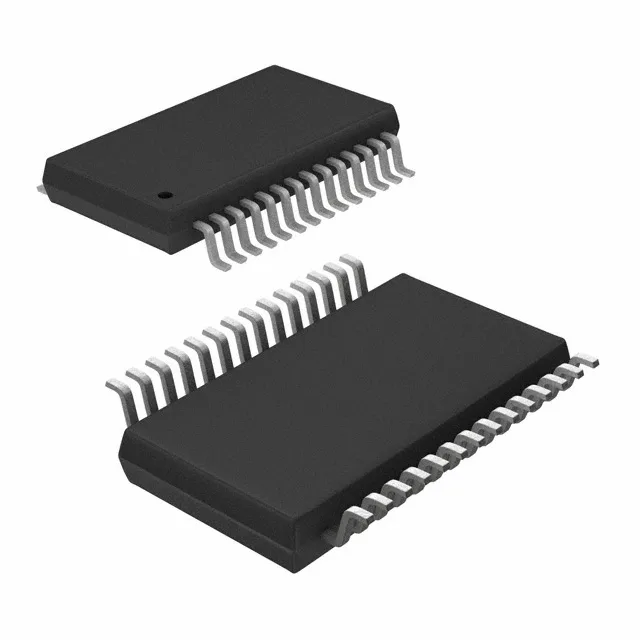
The 30-SSOP package (0.209-inch body width, 5.30 mm) is a surface-mount narrow-body SSOP. The 0.65 mm pin pitch is manageable on a two-layer board, but the four 1 A output traces need adequate copper width — at least 0.5 mm per amp on 1 oz copper — to keep the IR drop and temperature rise in check.