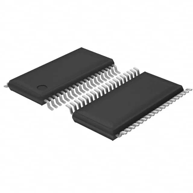
60 MHz C28x core with automotive qualification
On-chip peripherals include a 7-channel 12-bit ADC, PWM timers, a watchdog, brown-out detect, and serial interfaces (I²C, SCI, SPI, UART/USART).
What the 60 MHz and 64 KB Flash mean for a motor-control BOM
The 60 MHz clock on the C28x core delivers enough compute headroom for a single FOC (field-oriented control) loop on a PMSM or BLDC motor, including the current-regulation and speed PI controllers, plus a modest comms stack for CAN or UART telemetry. The 64 KB Flash (32K x 16) is the firmware budget — a typical sensorless FOC project with a few protection routines and a SCI bootloader fits, but a project adding Ethernet or a full fieldbus stack will bump into the ceiling. The 6K x 16 RAM holds the state variables, lookup tables, and a few frames of ADC data; it is tight for a large data-logging buffer.
Automotive temperature range and AEC-Q100 — the sourcing differentiator
The core supply at 1.8 V (1.71 V minimum) means a dedicated LDO on the board — the 3.3 V I/O rail powers the ADC and serial interfaces, while the core rail must be sequenced per the datasheet recommendation.
For a production BOM line this means no near-term LTB risk and continued factory support.