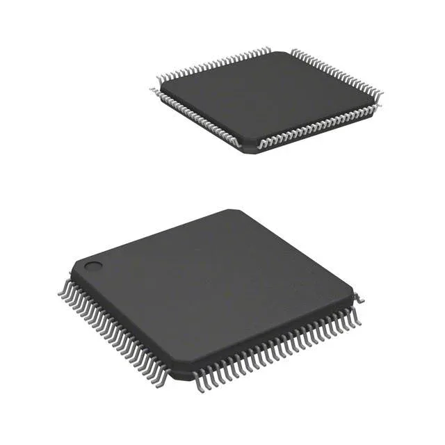
The TMS320F2801PZA-60: The 60 MHz clock rate on the C28x core translates to a 16.67 ns instruction cycle. For a typical 10 kHz PWM update with a 100-tap FIR filter, that leaves roughly 6000 cycles per loop — tight but workable if the code is compiled from the C2000 control-law library. The F280041PZQR sibling runs at 100 MHz, which buys 40% more headroom for the same loop, but also requires a 1.14 V core supply versus the 1.89 V rail here.
If the program targets an engine bay environment, a grade-0 derivative from the same C2000 family is needed.
Memory budget — 32 KB Flash, 6K x 16 RAM
The 32 KB Flash and 6K x 16 RAM are modest by current standards. A motor-control application with a field-oriented control (FOC) library, CAN stack, and a modest bootloader will fill the Flash to about 85%. The RAM budget is tight for large data arrays: a 200-point look-up table at 16-bit resolution consumes 400 bytes, leaving roughly 5 KB for stack and variables. Plan for a firmware size audit before committing the BOM.
Peripheral set — CAN, I²C, SCI, SPI, UART/USART
The 35 I/O lines include a CAN 2.0B controller, two I²C modules, two SCI (UART) ports, and one SPI. No LINbus is present, which is a gap for some body-electronics designs that use LIN for mirror or seat actuators. The CAN interface runs at up to 1 Mbps and is compliant with the J1939 and CANopen stacks used in heavy-vehicle and industrial automation.
100-LQFP package — layout and soldering notes
The supplier device package is 100-LQFP (14x14). The exposed pad (if present) should be connected to the ground plane with a via stitch for thermal relief; the core draws about 100 mA at 60 MHz, and junction temperature rise stays under 30°C with a 2-layer board.