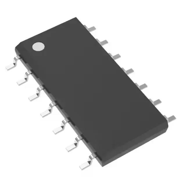
Quad CMOS op-amp for multi-channel signal chains
The TLV9064IDR packs four CMOS operational amplifiers into a 14-SOIC package, each channel delivering 10 MHz gain-bandwidth product and a 6.5 V/µs slew rate — enough bandwidth to handle sensor-conditioning loops up to several hundred kHz without the phase lag eating into the feedback margin. Rail-to-rail output swing means each amplifier can drive its output within millivolts of the supply rails, which matters when the ADC reference is the same 1.8 V to 5.5 V rail the op-amp runs on — no headroom lost to the output stage. Supply current is 538 µA total for all four channels, or about 135 µA per amplifier — this keeps the thermal budget low in a dense 14-SOIC layout where four channels share one package footprint.
Input-stage precision and drive capability
Input bias current is 0.5 pA typical — the CMOS gate leakage is negligible for high-impedance sources like photodiode front-ends or pH probe buffers where a bipolar input's nanoamp bias would shift the DC operating point. Input offset voltage is 300 µV maximum; for a quad pack this means the four channels track each other across temperature, so a multi-channel data-acquisition system does not require per-channel calibration if the offset is within the system's error budget. Each output can source or sink 50 mA — sufficient to drive the analog input of a successive-approximation ADC directly, or to bias a small relay coil through a current-limiting resistor without a separate buffer stage.
Industrial temperature range and supply flexibility
Rated for -40°C to 125°C ambient, the TLV9064IDR covers the full industrial temperature envelope — an engine-bay sensor interface or a rooftop solar inverter controller sees 105°C on the PCB and still has margin before the die hits the upper limit. Supply span from 1.8 V to 5.5 V means the same BOM position works in a 3.3 V system and a 5 V system; the rail-to-rail output ensures the full ADC code range is usable at either supply voltage. Surface-mount in the 14-SOIC (150-mil wide) footprint — the 3.90 mm body width fits standard SOIC land patterns, and the package is compatible with reflow profiles that peak at 260°C per J-STD-020.
Sourcing and lifecycle
RoHS3 compliant (2011/65/EU + 2015/863), with no restricted substances above the threshold — the part ships in Tape & Reel or Cut Tape, matching standard pick-and-place feeders for the 14-SOIC package.