2 MHz GBW, 3.4 V/µs slew — JFET quad for signal conditioning
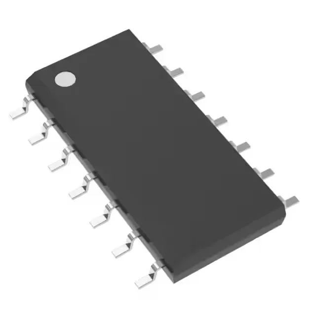
The TLE2064CD is a JFET-input quad operational amplifier from Texas Instruments, packing four independent amplifiers into a 14-SOIC package. The 2 MHz gain-bandwidth product and 3.4 V/µs slew rate define the large-signal bandwidth ceiling — for a 10 V output swing, the slew rate limits the full-power bandwidth to roughly 54 kHz, so keep the output step amplitude in mind when driving a fast ADC input or a multiplexed analog bus. Each channel draws 1.25 mA supply current, totalling 5 mA for the quad package — a reasonable power budget for a multi-channel signal chain running off a single 7 V to 36 V rail. The 4 pA typical input bias current makes it a natural fit for high-impedance sensor front-ends where a bipolar-input op-amp would pull the DC operating point off by tens of millivolts across a 10 MΩ source.
Active production, commercial temp, RoHS3 — sourcing reality
Sourced through independent distribution channels, the TLE2064CD is quoted to order against your BOM quantity.
Parametric fit — what the numbers mean for the bench
Input offset voltage is 900 µV typical — not a precision-grade figure, but adequate for general-purpose signal conditioning where the DC error budget allows a couple of millivolts. The 80 mA output current per channel can drive a 50 Ω load to within a volt of the rails, useful for driving a coaxial cable or a small relay coil directly. Supply span from 7 V to 36 V covers the common single-supply rails (5 V is below the minimum — this part needs at least ±3.5 V or a 7 V single rail) and dual-supply configurations up to ±18 V. The JFET input stage keeps the bias current in the picoamp range across the common-mode range, so the input error from source impedance is negligible even with a 1 MΩ source.