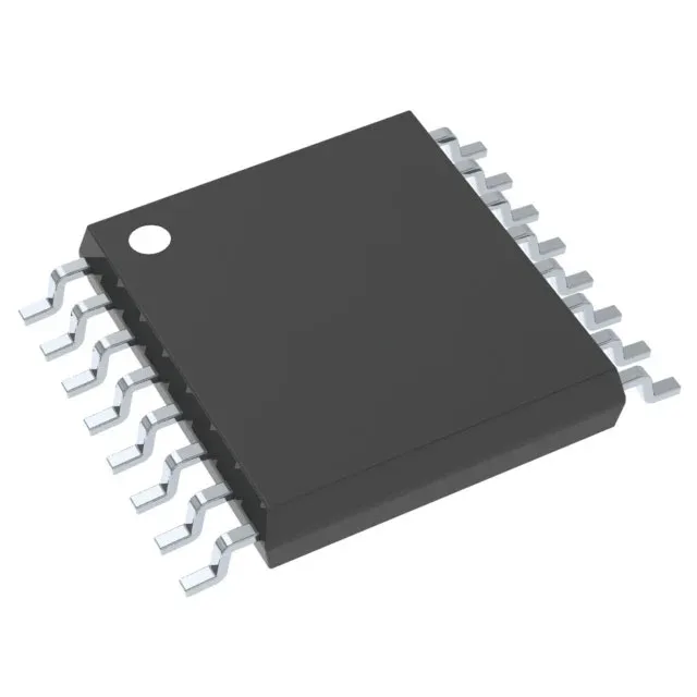
The TL494CPW is a fixed-frequency PWM controller that drives two external transistors in step-up, step-down, or step-up/step-down topologies — buck, boost, flyback, forward, full-bridge, half-bridge, or push-pull. Switching frequency is programmable from 1 kHz to 300 kHz. At the low end it drives line-frequency transformers in push-pull or half-bridge; at the high end it shrinks magnetics for a 100–200 kHz buck converter. The 45% max duty cycle per output prevents simultaneous conduction in push-pull stages — a deliberate design guard against core saturation.
Package, temperature, and board-fit checks
Housed in a 16-TSSOP (0.173-inch body width, 4.40 mm). The fine-pitch leads (0.65 mm) require a controlled reflow profile and solder-paste inspection — not a hand-solder part. Two transistor-driver outputs with positive output configuration drive external NPN or N-channel FETs. Dead-time control and frequency control are on-chip; no synchronous rectifier, so the secondary-side rectification is diode-based.
The base product number is TL494. No official TI successor or cross-reference has been issued for this variant.
How it compares to the UCC2806DWTR
The UCC2806DWTR is a close functional peer also from TI: a PWM controller with 50% max duty cycle (vs. 45% on the TL494CPW) and synchronous rectifier capability (the TL494CPW lacks this). The UCC2806 runs from an 8V supply (vs. 7V–40V) and is specified over –40°C to 85°C, giving it a wider temperature envelope. If your design needs synchronous rectification or industrial temperature range, the UCC2806DWTR is the cleaner fit; the TL494CPW wins on supply-range flexibility and lower cost for commercial-grade builds.