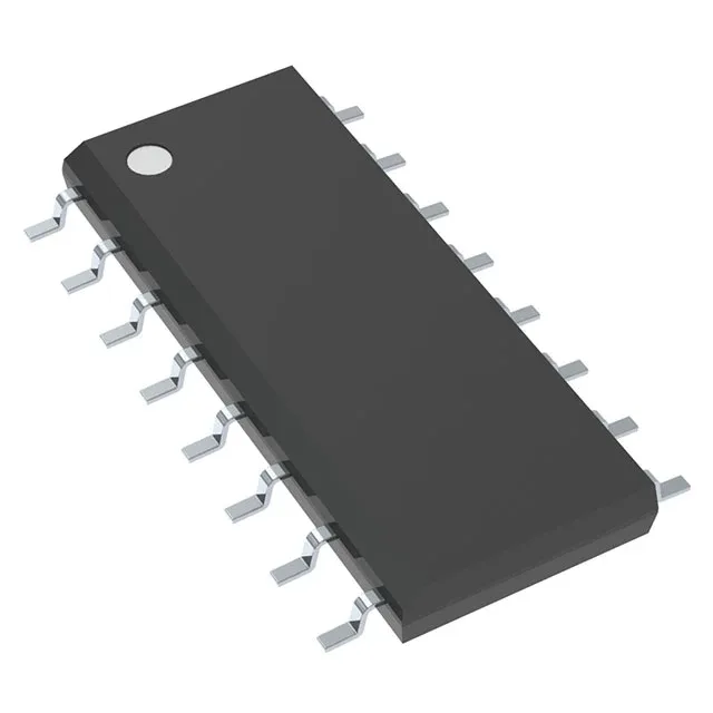
Texas Instruments TL494CDG4 — Power Management (PMIC / Gate Driver)

TL494CDG4 PWM Controller, 1kHz–300kHz, 7V–40V, 16-SOIC

MPNTL494CDG4
End of Life

Texas Instruments TL494CDG4 PWM controller, 16-SOIC, switching frequency 1kHz to 300kHz, 45% max duty cycle, 7V to 40V supply, 2 outputs, transistor driver output type.

Independent supplier — new & surplus stockAuthenticity-screened · ESD-safe packingListing updated Jul 2026

Specifications

TL494CDG4 specifications
ParameterValue
Output typeTransistor Driver
MountingSurface Mount
Voltage - supply (Vcc (Vdd))7V ~ 40V
Frequency - switching1kHz ~ 300kHz
I/O channels2
Output phases1
Duty cycle45%
Operating temperature0°C~70°C(TA)
PackageTube
FunctionStep-Up, Step-Down, Step-Up/Step-Down
TopologyBuck, Boost, Flyback, Forward Converter, Full-Bridge, Half-Bridge, Push-Pull
Clock syncNo
Case16-SOIC (0.154\", 3.90mm Width)
Control featuresDead Time Control, Frequency Control
Output configurationPositive
Synchronous rectifierNo

Product details

PWM controller for isolated and non-isolated topologies

The Texas Instruments TL494CDG4 is a fixed-frequency PWM controller that supports buck, boost, flyback, forward converter, full-bridge, half-bridge, and push-pull topologies. It operates from a 7V to 40V supply and delivers two transistor-driver outputs with a maximum duty cycle of 45% per output. The switching frequency range of 1kHz to 300kHz covers the typical operating band for offline flyback converters at the low end and push-pull or half-bridge designs at the high end. The 45% duty-cycle ceiling per output enforces dead time between the two output phases, which prevents transformer saturation in push-pull and half-bridge stages.

Supply rail and control features

The wide Vcc range of 7V to 40V allows the controller to be biased directly from the rectified DC bus in offline supplies without a separate auxiliary winding. The built-in dead-time control and frequency control pins give the designer independent adjustment of the output pulse width and the oscillator timing. The TL494CDG4 does not include a clock-sync input or synchronous rectifier drive — these are external additions when needed. The output configuration is positive, and the single-phase output drives two transistor stages internally.

Frequently asked questions

Can TL494CDG4 be used in a buck converter topology?

Yes. For a buck converter, the 45% maximum duty cycle per output is sufficient for step-down ratios that keep the on-time within that limit.

What is the maximum duty cycle of TL494CDG4?

The maximum duty cycle per output is 45%. This is a characteristic of the classic TL494 architecture and is designed to guarantee dead time between the two output phases in push-pull and half-bridge stages.

Is TL494CDG4 RoHS compliant?

The TL494CDG4 is the lead-free (RoHS-compliant) ordering code in the TL494 family. The 'G4' suffix indicates a green/RoHS-compliant finish from Texas Instruments.