The 25 MHz clock rate is the maximum CPU speed for this device. It sets the timing closure window for peripheral bus transactions and interrupt latency. For a 16-bit core, 25 MHz is a mid-range speed — enough for real-time control loops and communication protocol handling without pushing signal-integrity margins on a 5x5 mm BGA layout.
Memory and peripheral complement
128 KB of Flash and 8 KB of RAM suit firmware images that need moderate code space and a small data buffer — think bootloaders, sensor fusion algorithms, or Modbus slave stacks. Connectivity covers I²C, IrDA, SPI, and UART/USART, which covers the common serial interfaces for industrial sensor and actuator links.
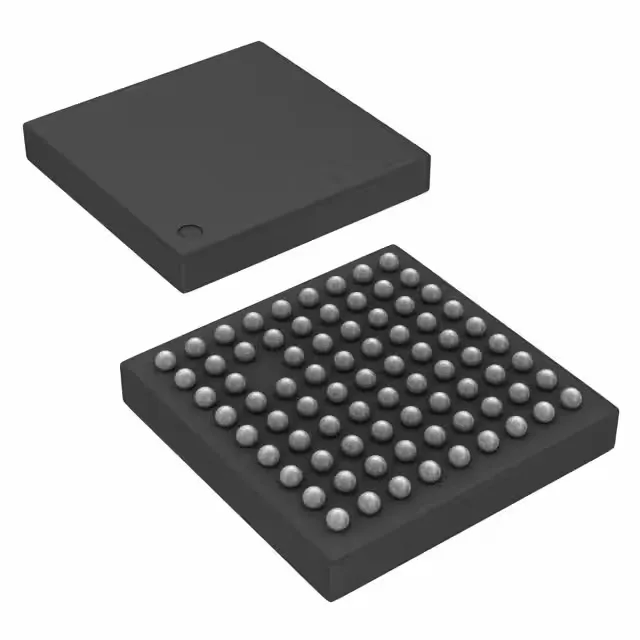
The 80-ball VFBGA (MicroStar Junior 5x5 mm) is a fine-pitch BGA. Rework is possible with a proper BGA station, but hand-soldering is not practical. The 53 I/O lines are distributed across the ball grid, so a layout review against the pinout map is essential before committing the board.