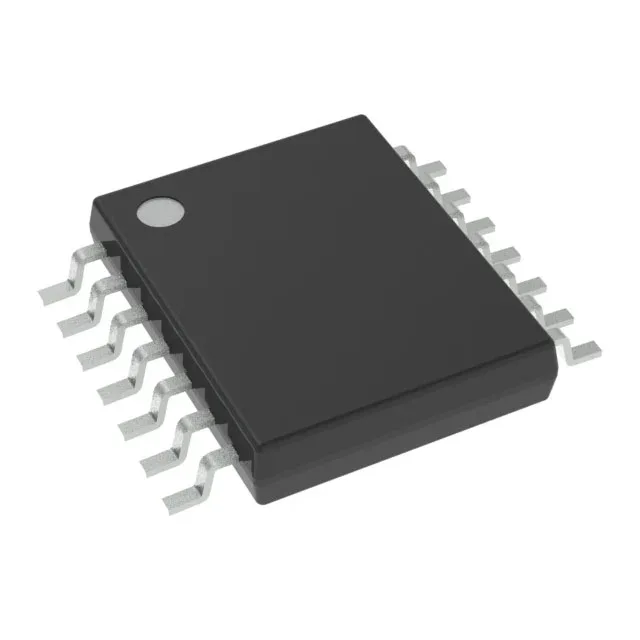
Quad XOR in a 14-TSSOP footprint
The SN74LVC86APWR: Each gate performs the XOR function: output goes high when the two inputs differ, making it the go-to cell for data comparison, parity generation/checking, encryption datapath mixing, and phase-detection in PLL feedback loops.
Propagation delay and drive — what 4.4 ns and 24 mA mean on the bench
Maximum propagation delay is 4.4 ns at 3.3 V with a 50 pF load. That sets the usable toggle rate ceiling: with a 4.4 ns delay, the gate can cleanly pass a 100 MHz clock edge — but the actual system data rate depends on the cumulative delay through the XOR chain plus the output rise time into the downstream load. For a single-gate path, budget 4.4 ns tPD plus ~2 ns rise time (into 15 pF) for a safe 60-80 MHz throughput. Output sink and source both rated 24 mA — enough to drive a standard CMOS input fan-out of 10-15 loads without external buffers, or to directly switch an LED indicator through a series resistor. The symmetric drive also keeps the high-to-low and low-to-high transition times matched, which matters for maintaining duty cycle in clock distribution. Quiescent current sits at 1 µA max. In a battery-powered system that gates the XOR supply when idle, the standby drain is below the self-discharge rate of a CR2032 coin cell — no need for a separate load switch.
Temperature grade and voltage thresholds — where this part runs
An engine-bay ECU or a solar-inverter controller that sees 105°C ambient still has 20°C of margin before the junction hits the 125°C ceiling. Input logic thresholds are LVCMOS: low level 0.7 V to 0.8 V, high level 1.7 V to 2 V. At 3.3 V VCC, the high threshold is 1.7 V, so a 2.5 V CMOS output drives it cleanly. At 1.8 V VCC, the low threshold is 0.7 V — a 1.2 V output from a lower-voltage FPGA I/O bank may not guarantee a logic-low without a level translator.
Active production, no end-of-life signal
No official successor or second-source listed. The 74LVC family is mature and stable — the XOR function in this package has no direct pin-compatible drop-in from other manufacturers, so confirm the BOM position before committing the board.