Memory budget — what 1 KB Flash and 128 B RAM mean for your firmware
1 KB of Flash and 128 bytes of RAM is a constrained environment. This MCU is not for a multi-threaded RTOS or a TCP/IP stack — it is sized for a single polling loop, a state machine, or an interrupt-driven sensor readout. Typical firmware fits: a temperature/humidity sensor polling I²C every second, a battery fuel-gauge algorithm, a simple PWM fan controller, or a digital potentiometer interface. The 256-byte information memory segment (part of the Flash block) can hold calibration constants or boot parameters that survive power cycles. The 16-bit core and 16 MHz clock provide enough throughput for 10 ksps ADC conversions with software filtering. The RAM ceiling means look-up tables stay small.
10-channel 16-bit ADC — direct sensor interface without external silicon
Channel count of 10 matches the 10 available I/O pins — the ADC mux shares the port pins, so every analog input reduces digital I/O by one. Plan your pin allocation early: if you need all 10 analog channels, you have zero GPIO left for pushbuttons or status LEDs. The 16-bit result is stored in two 8-bit registers per channel; read them in sequence within the same ADC interrupt to avoid a mid-read update.
Sourcing and lifecycle — active production, standard channel
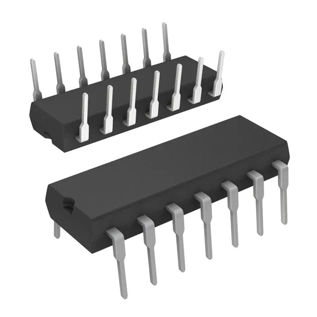
No minimum order quantity constraints beyond standard reel or tube multiples — the 14-PDIP ships in tubes.