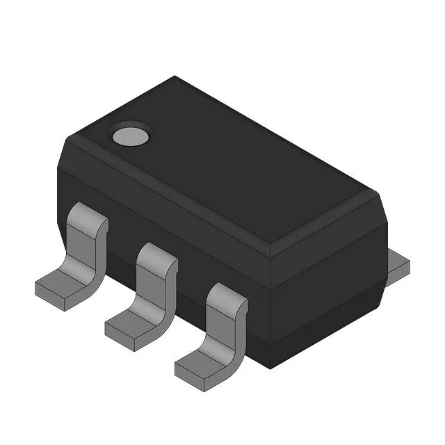
Texas Instruments LM7121IM5 — Memory (DRAM / SRAM / Flash / EEPROM)

LM7121IM5 Voltage Feedback Op-Amp, 1300 V/µs Slew Rate

MPNLM7121IM5
End of Life

Texas Instruments LM7121IM5, Voltage Feedback Amplifier, 1 Circuit, Slew Rate 1300 V/µs, -3 dB Bandwidth 235 MHz, Supply 4.5 V to 33 V, SOT-23-5 Package, -40°C to 85°C.

$2.98Ref. price · indicative, final on quote
PackagingSC-74A, SOT-753
StockContact for availability
MOQ1 pcs
  • 100% new & originalTraceable channels only — no refurbs, no pulls, no remarked parts.
  • Date & lot codes on quoteStated per line before you commit; label photos on request.
  • MSL-compliant ESD packingMoisture-sealed bags with indicator cards; reels photo-verified.
  • PayPal buyer protectionPay by T/T, PayPal or Payoneer — card payments covered end to end.

Specifications

LM7121IM5 Technical Specifications
ParameterValue
Mounting typeSurface Mount
Amplifier typeVoltage Feedback
Voltage - input offset900 µV
Voltage - supply span4.5 V
Current - supply5.3mA
Current - input bias5.2 µA
Current - output (Channel)71 mA
Operating temperature-40°C ~ 85°C
-3db bandwidth235 MHz
Gain bandwidth product175 MHz
PackageBulk
Slew rate1300V/µs
CaseSC-74A, SOT-753
Number of circuits1

Product details

Key ratings and what they mean for the BOM

The 1300 V/µs slew rate and 235 MHz bandwidth suit video line drivers and high-speed data acquisition front-ends. Supply voltage spans 4.5 V to 33 V.

Package and mounting

The LM7121IM5 is supplied in a SOT-23-5 surface-mount package. The footprint matches the standard SOT-23-5 land pattern. The bulk packaging ships in tubes or trays.

Frequently asked questions

Can LM7121IM5 be used in high-speed signal conditioning applications?

Yes, the 1300 V/µs slew rate and 235 MHz bandwidth make it suitable for video amplification, pulse shaping, ADC drivers, and other high-speed signal conditioning tasks where a single-supply voltage feedback topology is acceptable.

What is the pinout of LM7121IM5?

The LM7121IM5 uses the standard SOT-23-5 pinout for single op-amps: pin 1 is output, pin 2 is V–, pin 3 is non-inverting input, pin 4 is inverting input, and pin 5 is V+. This matches the pin arrangement of many SOT-23-5 op-amps, simplifying board layout when cross-shopping.