Clock synthesis for multi-domain boards
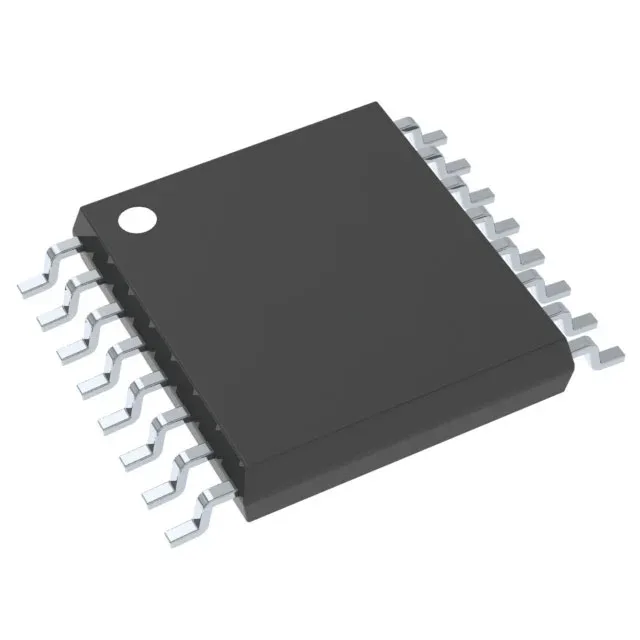
The CDCEL925PW: The integrated PLL includes a bypass mode — when bypassed, the input clock passes directly to the outputs, useful for system test or low-jitter paths where the PLL's phase noise is undesirable. The 1:5 input-to-output ratio means one reference clock feeds five independent clock domains, each programmable via the device's serial interface. This suits boards where a single oscillator must drive multiple ICs — an FPGA core clock, a DDR memory reference, and a gigabit Ethernet PHY, for example — without adding separate crystal cans for each rail.
Supply and temperature constraints for the BOM
If your board uses 2.5V or 3.3V for the clock generator, you will need a local LDO.