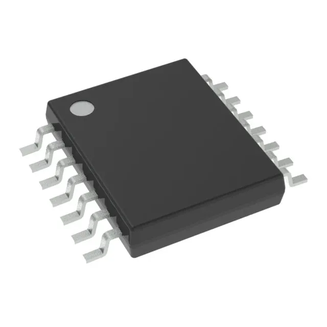
Texas Instruments CDCE913PWG4 — Clock & Timing ICs

TI CDCE913PWG4 Spread Spectrum Clock Driver, 230 MHz

MPNCDCE913PWG4
End of Life

Texas Instruments CDCE913PWG4 Spread Spectrum Clock Driver, PLL Yes with Bypass, LVCMOS Input/Output, 230 MHz max, 14-TSSOP package, Tube.

$178.8000Ref. price · indicative, final on quote
Independent supplier — new & surplus stockAuthenticity-screened · ESD-safe packingListing updated Aug 2026

Specifications

CDCE913PWG4 specifications
ParameterValue
TypeSpread Spectrum Clock Driver
MountingSurface Mount
Supply voltage1.7V ~ 1.9V, 2.3V ~ 3.6V
Frequency - max230MHz
Operating temperature-40°C~85°C
PLLYes with Bypass
InputLVCMOS, Crystal
OutputLVCMOS
PackageTube
Case14-TSSOP (0.173\", 4.40mm Width)
Divider (Multiplier)Yes/Yes
Number of circuits1
Ratio - Input:Output1:3
Differential - Input:OutputNo/No

Product details

Clock-engineer decisions: PLL bypass and spread-spectrum fit

The CDCE913PWG4: The integrated PLL includes a bypass mode, letting you route a clean reference through the chip without engaging the synthesis loop — useful when the downstream device needs a jitter-free clock for a critical interface. As a spread-spectrum clock driver, it modulates the output frequency to reduce peak EMI at the fundamental and harmonics, which can lower the cost of shielding or ferrite beads on a densely routed board. The 1:3 input-to-output ratio means a single LVCMOS or crystal source fans out to three LVCMOS clock lines, each programmable up to 230 MHz via the internal divider chain.

Supply rails and temperature envelope

The dual supply range — 1.7 V to 1.9 V and 2.3 V to 3.6 V — lets the core run at a lower voltage while the I/O section matches the logic level of the receiving device, saving a level translator in mixed-voltage designs.

Frequently asked questions

What does the PLL bypass mode do on the CDCE913PWG4?

The PLL bypass mode lets the input clock pass through the device without frequency synthesis, delivering a clean reference clock to the outputs when the jitter of the locked loop is not desired — for example, when clocking a low-jitter ADC or FPGA transceiver.

What is the maximum output frequency of the CDCE913PWG4?

The device supports a maximum output frequency of 230 MHz, limited by the internal PLL and divider chain, with LVCMOS outputs capable of driving standard 50-ohm terminated traces at that speed.