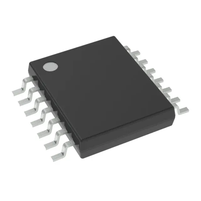
PLL with bypass — why it matters for the timing tree
The CDCE813QPWRQ1 integrates a PLL with a bypass path, meaning the output can either lock to the reference for jitter cleaning or pass the input through unmodified. This is the feature that lets a single part serve as both a frequency synthesizer and a clean clock repeater — useful when a noisy reference needs cleaning before it reaches the downstream PHY, or when the system boots with an un-locked PLL and needs a clean bypass clock until lock is achieved.
230 MHz ceiling and 1:3 fan-out
The maximum output frequency of 230 MHz covers common automotive serial interfaces (CAN-FD, FlexRay, Ethernet at 100BASE-T1) and most MCU clock inputs. The 1:3 input-to-output ratio means one crystal or LVCMOS reference drives three independent clock outputs — enough to feed a main SoC, a transceiver, and a monitoring controller without an external fan-out buffer.
Automotive temperature range and supply rail
The supply range is 1.7V to 1.9V — a 1.8V nominal rail with ±5% tolerance fits, but a wider-tolerance rail (e.g., ±10%) will drift out of spec at the low end. Plan the regulator accordingly.