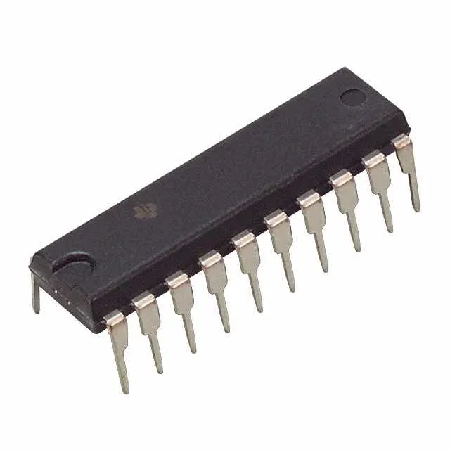
85 MHz clock ceiling and 13.5 ns propagation delay
The CD74ACT273E: This sets the data-rate ceiling for the bus — the output rise time into the load capacitance adds to the delay, so the actual toggle rate at the receiver is lower than the bare clock spec suggests. The 8 µA quiescent current keeps the standby power negligible in systems that gate the clock.
Military temperature grade and through-hole package
Housed in a 20-pin DIP (0.300-inch, 7.62 mm pitch) with a through-hole mounting footprint. The 20-PDIP supplier package mates with standard DIP sockets or wave-solder boards; the 0.100-inch pin spacing is compatible with breadboard prototyping.
Active lifecycle and compliance status
The 10 pF input capacitance per channel is typical for the 74ACT family; the positive-edge trigger and master-reset function are standard for this octal flip-flop architecture.