What the clamping and breakdown ratings mean for your protection margin
The 1.5KE170CH: The minimum breakdown voltage is 153 V, and the maximum clamping voltage is 244 V. The gap between these two figures defines the protection window: a transient that exceeds 153 V will begin to conduct, but the load sees no more than 244 V across the diode. For a 138 V nominal rail, this clamping level keeps the spike within the typical 250 V abs-max rating of downstream 150 V-class MOSFETs and ICs. The 1500 W peak pulse rating is the product of the clamping voltage and the peak pulse current at the 10/1000 µs test condition. In a real application, the actual power dissipated depends on the surge waveform duration and the source impedance — shorter pulses (e.g. 8/20 µs) allow higher peak current before the junction temperature limit is reached.
Package and mounting — DO-201 axial leaded
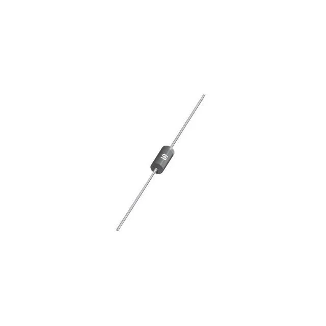
Housed in a DO-201AA (DO-27) axial-lead package, the 1.5KE170CH is a through-hole device intended for point-to-point wiring or PCB mounting with the leads formed to the hole spacing. The axial body allows the diode to be inserted in either orientation — polarity is not an issue since it is bidirectional. The DO-201 package has a larger body than the smaller DO-41 or SMA packages, which translates to lower thermal resistance to ambient. For repetitive pulse applications, the lead length and copper pad area on the PCB set the effective junction-to-ambient thermal path.