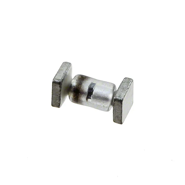
What 1N6119AUS standoff, breakdown and clamping ratings mean
The reverse standoff voltage of 27.4V defines the working window — the circuit sees less than this across the diode in normal operation, so it stays off and contributes no leakage until a transient pushes it into avalanche. At 34.2V minimum breakdown the device enters conduction in the reverse direction, and the clamping characteristic limits the peak at the protected node to 49.9V when the 10A peak pulse current flows for the standard 10/1000 µs waveform. The 500W peak pulse rating is the surge-handling ceiling for that event — design the board trace and bulk capacitance to deliver that current to the diode before the clamp settles, and the downstream load stays within its abs-max during the event. Rated for general-purpose use — the 1N6119 base series is a long-running Zener/TVS family, not optimised for dedicated power-line protection roles. The single bidirectional channel means it handles transients in both polarities without a polarity requirement on the line.
SQ-MELF B package on surface-mount boards
The SQ-MELF B is a cylindrical surface-mount package — the anode and cathode ends are the termination bands, and the body diameter and lead standoff define the solder joint geometry. Board footprint calls out the pad width and spacing directly from the package outline; the seated height is set by the body diameter plus the termination thickness. Reflow profile follows the standard SnPb or lead-free solder window for the package size — check the Semtech assembly note for the specific soak and peak temperature targets for this body style. The bulk pack variant ships without a reel or tape — the mechanical termination integrity is identical to the tape-and-reel version of the same MELF code, so the electrical spec is unaffected by the packaging format.