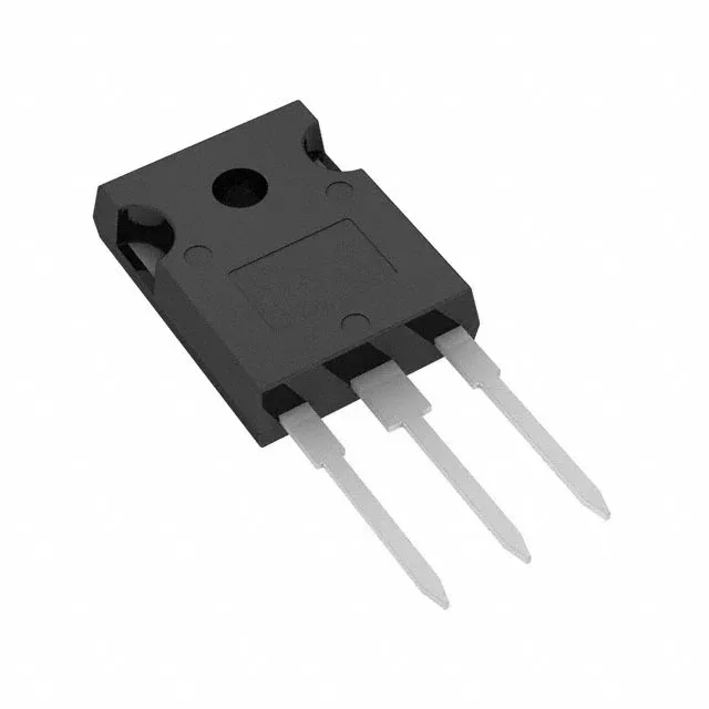
Active production — AEC-Q101 SiC power FET for traction and PFC
Qualified to AEC-Q101, the SCT3017ALHRC11 is certified for automotive-grade reliability stress and temperature cycling — the standard for under-hood and chassis-domain power stages in traction inverters, DC-DC converters, and on-board chargers.
On-resistance and gate charge — motor-drive conduction and switching budget
Maximum on-resistance is 22.1 mOhm at 47 A drain current with 18 V gate drive. This is the conduction-loss figure to use in thermal calculations for a motor-drive output stage or PFC boost: at 47 A the resistive loss per device is roughly 49 W, which combined with the 427 W power dissipation ceiling tells you the heatsink and airflow required to keep junction temperature below the 175 °C absolute maximum. Total gate charge is 172 nC at Vgs = 18 V. For a switching frequency of 20 kHz in a traction inverter, the gate-driver must supply roughly 3.4 mA average current just to charge and discharge the gate capacitance — plus the driver's own quiescent draw. The 172 nC figure also sets the crossover time in the miller plateau; a driver with insufficient peak current extends the switching interval and raises turn-on and turn-off losses. Gate-source voltage is rated +22 V / -4 V absolute maximum. The asymmetric negative rail means the gate-drive supply should clamp below -4 V to avoid oxide stress during the off-state, particularly in half-bridge topologies where the low-side FET sees a negative Vgs spike during the high-side turn-on transient.
Threshold voltage and temperature margin
Maximum threshold voltage is 5.6 V at 23.5 mA drain current. With a typical gate-drive voltage of 15-18 V, the gate overdrive is roughly 10-12 V above Vgs(th), keeping the FET in the ohmic region across the full load range.