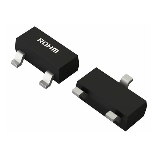
ROHM Semiconductor BSS4130AT116 — Microcontrollers & Processors (MCU / MPU / DSP)

BSS4130AT116 NPN Transistor, 30V 1A SOT-23, 400MHz fT

MPNBSS4130AT116
End of Life

ROHM BSS4130AT116 NPN transistor, 30 V Vce, 1 A Ic, 400 MHz fT, hFE 270 @ 100 mA, Vce(sat) 350 mV @ 500 mA, SOT-23-3 package, 150°C junction temp.

$0.43Ref. price · indicative, final on quote
PackagingTO-236-3, SC-59, SOT-23-3
StockContact for availability
MOQ1 pcs
  • 100% new & originalTraceable channels only — no refurbs, no pulls, no remarked parts.
  • Date & lot codes on quoteStated per line before you commit; label photos on request.
  • MSL-compliant ESD packingMoisture-sealed bags with indicator cards; reels photo-verified.
  • PayPal buyer protectionPay by T/T, PayPal or Payoneer — card payments covered end to end.

Specifications

BSS4130AT116 Technical Specifications
ParameterValue
Mounting typeSurface Mount
FET typeNPN
Voltage - collector emitter breakdown30 V
Current - collector (Ic)1 A
Current - collector cutoff100nA (ICBO)
DC current gain (hFE) (Min) @ ic, vce270 @ 100mA, 2V
Power - max200 mW
Frequency400MHz
Operating temperature150°C (TJ)
PackageTape & Reel (TR); Cut Tape (CT)
CaseTO-236-3, SC-59, SOT-23-3
Vce saturation (Max) @ ib, ic350mV @ 25mA, 500mA

Product details

What this NPN transistor brings to the board

The ROHM BSS4130AT116 is a general-purpose NPN transistor rated for 30 V collector-emitter breakdown and 1 A continuous collector current, packed in a SOT-23-3 footprint. With a transition frequency of 400 MHz and a minimum DC current gain of 270 at 100 mA, it handles moderate-speed switching and amplification jobs without needing excessive base drive. The 150°C junction temperature rating means it can sit in warm spots — think engine-bay electronics, industrial control boxes, or power supply secondary-side circuits — without derating headaches.

Pulling 1 A through a SOT-23 package is a thermal challenge: the 200 mW power limit means you cannot run that current continuously at full Vce. For a saturated switch at 350 mV drop, 1 A gives about 350 mW — already past the limit. So this part is really a 500 mA to 800 mA continuous switch in practice, with the 1 A rating for pulsed or low-duty-cycle loads. The low Vce(sat) of 350 mV at 500 mA keeps dissipation under 175 mW, which the package handles comfortably with standard PCB copper.

Gain and speed — field-fit notes

A minimum hFE of 270 at 100 mA means a 3.3 V logic output can drive this transistor into saturation with a 1 kΩ base resistor — no extra driver stage needed. The 400 MHz transition frequency is fast enough for 1–2 MHz switching regulators or signal buffers; for higher-frequency RF work you would look at a dedicated RF transistor. The 100 nA collector cutoff keeps leakage negligible at room temp, though it will climb with junction temperature — budget for that if the ambient is above 85°C.

Frequently asked questions

What is the maximum collector current of BSS4130AT116?

The maximum continuous collector current (Ic) is 1 A. In practice, the 200 mW power limit and SOT-23 thermal constraints mean continuous operation is typically limited to 500–800 mA at low Vce.