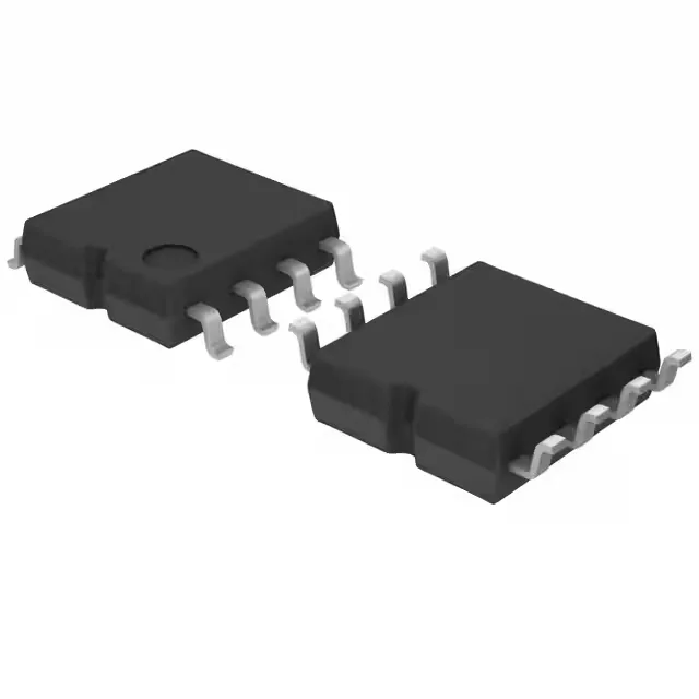
ROHM Semiconductor BR25H256F-2ACE2 — Discrete Semiconductors

BR25H256F-2ACE2 ROHM 256Kbit SPI EEPROM, AEC-Q100, 8-SOP

MPNBR25H256F-2ACE2
End of Life

ROHM Semiconductor Automotive, AEC-Q100 series EEPROM, BR25H256F-2ACE2, 256Kbit SPI 10MHz, 2.5V-5.5V, -40°C to 125°C, 8-SOP.

$2.78Ref. price · indicative, final on quote
Packaging8-SOIC (0.173", 4.40mm Width)
StockIn Stock (22)
Lead timeIn Stock wk
MOQ1 pcs
  • 100% new & originalTraceable channels only — no refurbs, no pulls, no remarked parts.
  • Date & lot codes on quoteStated per line before you commit; label photos on request.
  • MSL-compliant ESD packingMoisture-sealed bags with indicator cards; reels photo-verified.
  • PayPal buyer protectionPay by T/T, PayPal or Payoneer — card payments covered end to end.

Specifications

BR25H256F-2ACE2 Technical Specifications
ParameterValue
SeriesAutomotive, AEC-Q100
Memory typeNon-Volatile
Mounting typeSurface Mount
Voltage2.5V ~ 5.5V
Frequency10 MHz
Memory interfaceSPI
Operating temperature-40°C ~ 125°C (TA)
PackageTape & Reel (TR); Cut Tape (CT)
TechnologyEEPROM
Memory size256Kbit
Memory formatEEPROM
Case8-SOIC (0.173\", 4.40mm Width)
Memory organization32K x 8
Write cycle time - word, page4ms

Product details

Package and board-fit for the 8-SOP

The BR25H256F-2ACE2 comes in an 8-SOIC (0.173", 4.40mm width) body, supplier device package 8-SOP. Surface-mount, 1.27 mm pitch — the footprint is standard enough that a rework station can lift this part without lifting the pad, provided the board has been baked to MSL spec before the hot air hits it. At 10 MHz SPI clock, the bus timing margins are comfortable for a 4-layer board with short traces; a 2-layer layout works if the SPI trace is kept under 50 mm and away from switching noise.

Temperature grade and the under-hood decision

An engine-bay ECU or transmission controller that sees 105°C on a summer-grade road still has 20°C of margin before the silicon hits its abs-max junction. The 256Kbit density (organized 32K x 8) holds calibration tables, fault logs, or VIN data that must survive a power cycle. Write cycle time is 4 ms per word or page — budget this into the firmware update routine. A full 256Kbit rewrite at 4 ms per page (32 pages of 8 bytes each) takes about 128 ms; the part is busy during that window and the SPI bus must not be accessed.