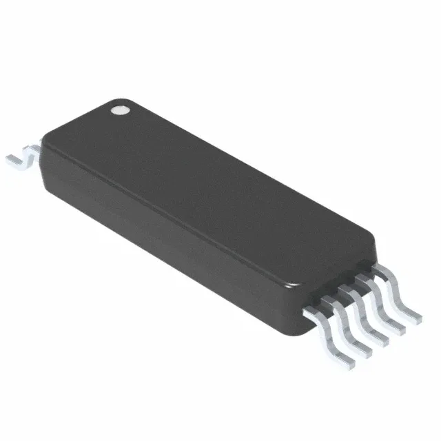
The BM61S41RFV-CE2 is a single-channel isolated gate driver from ROHM, qualified to AEC-Q100 for automotive use. It delivers 4 A peak source and sink current, enough to drive the gate of a medium-power IGBT or SiC MOSFET through the Miller plateau without excessive switching loss. Isolation is rated at 3750 Vrms, which covers the basic insulation requirement for a 400 V battery or 800 V DC-link in an automotive traction inverter — the reinforced isolation margin depends on the working voltage and pollution degree, but this figure is the certifiable withstand level per UL. Common-mode transient immunity is specified at a minimum of 100 kV/µs. That means the output state does not glitch when the switching node slews at 50 V/ns — a real concern in fast-switching SiC designs where the half-bridge midpoint jumps by hundreds of volts in a few nanoseconds.
Speed and timing — what 65 ns propagation delay buys you
Maximum propagation delay is 65 ns in both directions, with a pulse-width distortion of 60 ns max. For a 100 kHz switching frequency, the dead-time budget must account for this spread — the controller's dead-time setting should be at least 100 ns above the driver's maximum delay mismatch to avoid shoot-through. Rise and fall times are 15 ns typical into a capacitive load. This pairs with the 4 A output to charge the gate capacitance quickly, keeping the switching transition within the linear region of the IGBT or SiC device.
Temperature range and supply — where it works
The output supply range is 16 V to 24 V — this matches the typical gate-drive bias rail derived from a 12 V battery via a boost converter, or from a dedicated 18 V or 20 V supply.
Housed in a 10-SSOP (0.315-inch body width, 8.00 mm wide) with the supplier device code 10-SSOP-BW. The 1.27 mm pitch is layout-friendly — a two-layer board with adequate clearance under the package handles the 3750 Vrms isolation creepage, but the SSOP footprint demands a solder mask defined pad to avoid bridging.