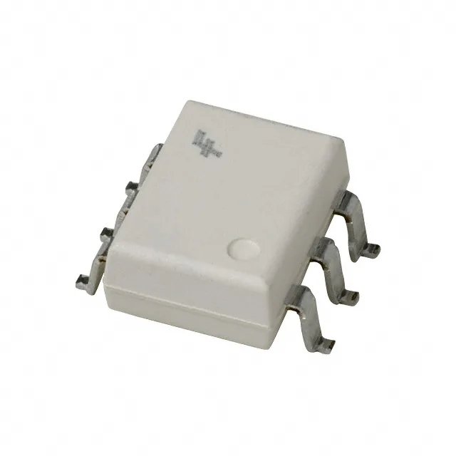
Triac driver for AC load switching
The onsemi MOC3073SR2M is a single-channel random-phase triac output optoisolator in a 6-SMD Gull Wing package. It provides 4170 Vrms isolation between the low-voltage control side and the 800 V off-state rated AC load side, making it suitable for switching 240 VAC loads with margin for mains transients. Because it lacks a zero-crossing circuit, the output triac can be triggered at any point in the AC waveform — this is the key distinction for phase-angle control applications like dimmers, soft-starters, or heater power regulators.
LED drive and noise immunity
Forward voltage is 1.18 V typical at 60 mA max DC forward current. Static dV/dt immunity is a minimum of 1 kV/µs. In an inductive load environment — a motor contactor or relay coil — this prevents the triac from falsely triggering on the voltage spike at commutation. Typical hold current is 540 µA. If the load current drops below this near the AC zero-cross, the triac may self-commutate; this matters for very low-power loads or when using the part in a snubberless design.
UL approved — the agency listing is on the datasheet, which covers the safety certification needed for mains-isolated designs.
The 6-SMD Gull Wing package has a 0.50 mm lead pitch typical for this family. The gull-wing leads are visible for solder inspection, and the package body stands off the board slightly, aiding cleaning and conformal coating. Surface-mount assembly — no through-hole holes needed on the PCB. The creepage distance between input and output pins across the package surface meets the 4170 Vrms isolation rating, but the PCB layout must maintain the same clearance under the component.