What the 60 MHz core and 128 KB Flash mean for your motor-control loop
The NXP MC56F8345MFGE is a 16-bit MCU built around the 56800E core — a DSP/MCU hybrid that runs a single-cycle multiply-accumulate, so a PID loop or sensorless observer fits in a few dozen instructions without a separate DSP. The 60 MHz clock gives you a 16.67 ns instruction cycle, which is enough headroom for a 20 kHz current-control loop with room left for CAN messaging and fault handling. Program memory is 128 KB of Flash (64K x 16), and the 6K x 16 RAM holds one or two motor-control data structures plus a modest stack — not enough for a full RTOS with multiple tasks, but fine for a foreground/background scheduler.
Peripheral set — CAN and PWM without external glue
This part integrates a CANbus controller, a PWM module, a temperature sensor, a POR, and a watchdog timer (WDT). The PWM is the key block for motor-drive applications — three-phase complementary outputs with dead-time insertion, directly driving an IGBT or MOSFET gate-driver stage. The CAN interface handles the fieldbus link to a PLC or drive controller. The 49 I/O lines leave room for encoder inputs, Hall-effect sensors, and a few discrete signals. The 16-channel 12-bit ADC (A/D 16x12b) samples current-sense resistors or voltage dividers without an external ADC.
Temperature range and package — industrial and under-hood ready
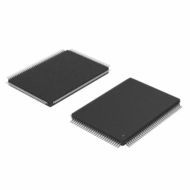
The 128-LQFP package (14x20 mm body) is a standard fine-pitch surface-mount footprint.