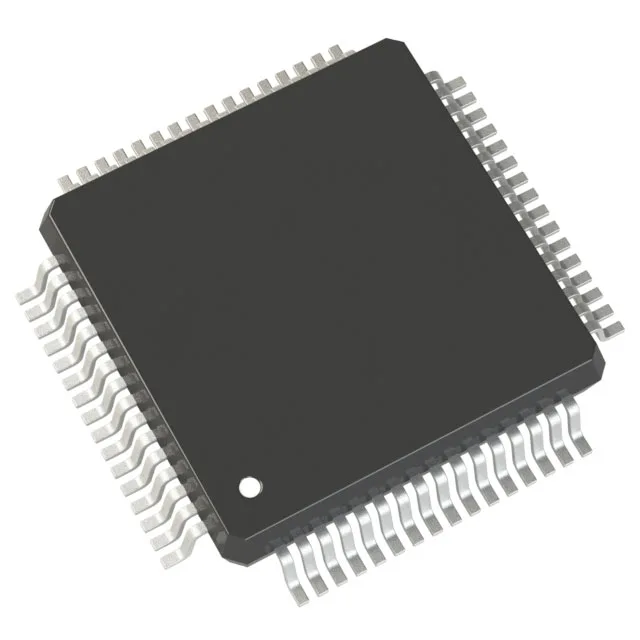
32 MHz 56800E core — DSP math on a 16-bit MCU budget
The MC56F8027VLHR runs a 56800E core at 32 MHz, a 16-bit architecture that blends MCU control logic with DSP-style multiply-accumulate and bit-reversal addressing — the kind of math a field-oriented motor-control loop or a digital power-supply compensator needs every PWM cycle. On-chip memory is 32 KB of flash (16K x 16) and 2K x 16 of RAM. For a typical sensorless BLDC motor-control firmware — Hall or BEMF observer, PI current loops, speed ramp — the flash holds the application plus a modest bootloader, and the RAM covers the state variables and a few circular buffers without spilling to external memory.
Peripheral set for motor-drive and power-conversion control
The part carries a PWM module with fault inputs, a POR (power-on reset) monitor, and a watchdog timer — the three essentials for a standalone motor-drive controller that must fail safe on a brownout or a code hang. Connectivity covers I2C, LINbus, SCI (UART), and SPI — enough to talk to an external encoder, a Hall sensor, a current-sense amplifier, or a host controller on a LIN or SCI bus. The 53 general-purpose I/O lines handle the gate-driver interface, fault inputs, and status LEDs without a port expander. The analog front end is a 16-channel, 12-bit ADC and a dual 12-bit DAC. In a motor-drive BOM, the ADC samples phase currents and DC-bus voltage; the DAC can output a reference or a test point for the current-loop setpoint. The 12-bit resolution (4096 counts) is adequate for 1 % current regulation in most industrial drives.
Industrial temperature grade and package fit
No BGA, no hidden solder joints — a standard hot-air rework station can replace it, and the leads are accessible for scope probing during bring-up.
Lifecycle and sourcing — active, no LTB pressure
Available in Tape & Reel (TR) for production pick-and-place or Cut Tape (CT) for prototype quantities.