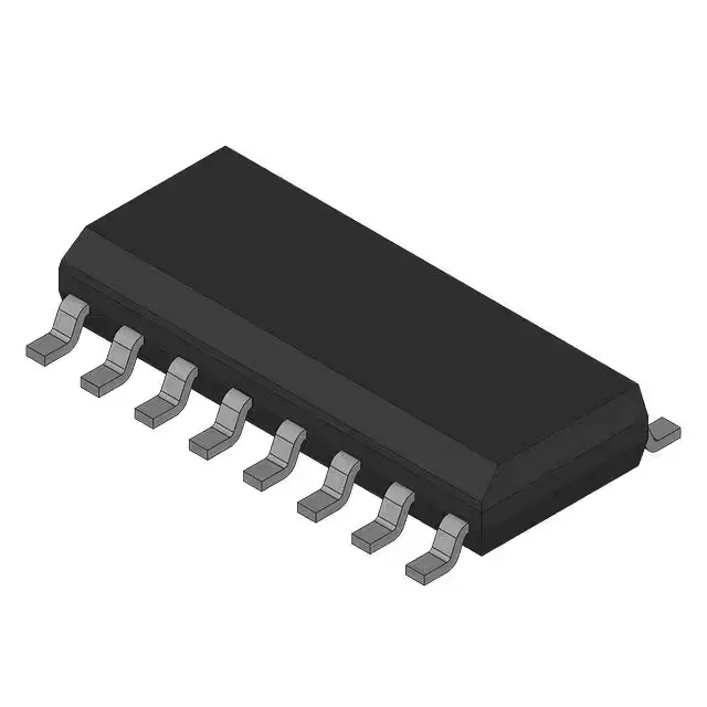
Package and board-fit — 14-SOIC with 1A per channel
The MIC2507BM TR: Each of the four outputs is rated for 1 A continuous, with a typical Rds(on) of 120 mOhm — at 1 A the conduction loss is 120 mW per channel, which sums to 480 mW for all four channels. The 14-SOIC copper pad on the board should be sized to keep the junction below the 85°C ambient ceiling. The switch operates over a load voltage range of 2.7 V to 7.5 V and does not require a separate Vcc/Vdd supply — the gate drive is derived from the load rail. The output configuration is high-side, so the switch sits between the supply and the load, with the N-channel FET pulling the output up when enabled. The input is non-inverting and the interface is a simple On/Off logic pin per channel.
Protection and switching behaviour
Fault protection includes adjustable current limiting and over-temperature shutdown — the current limit is set with an external resistor, so the trip threshold can be tailored to the load. The slew-rate controlled turn-on reduces inrush current into capacitive loads, and the status flag output signals over-current or thermal fault conditions to the host controller. These features make the part suitable for USB ports, hot-swap supplies, and general-purpose power distribution where a controlled ramp and fault reporting are needed. The switch type is general purpose, and the ratio of input to output is 1:1 — each input controls one output directly.