3 A peak drive, 13 ns rise — what it means for IGBT switching
The MCP14A0301-E/MS delivers 3 A peak source and sink current, which is the current available to charge and discharge the IGBT gate capacitance during switching transitions. With 13 ns typical rise time and 12 ns fall time into a standard test load, this driver can slam a medium-power IGBT's gate past the Miller plateau fast enough to keep switching losses in check up to a few hundred kilohertz, depending on the total gate charge. Supply voltage spans 4.5 V to 18 V, covering the common gate-drive rails for IGBTs in motor drives, power supplies, and inverters.
Single-channel, high-side or low-side — flexible topology fit
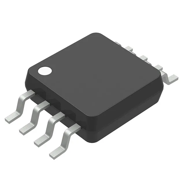
Driven configuration is selectable as high-side or low-side, so a single part can serve as the bootstrap-side driver in a half-bridge leg or as a standalone low-side switch driver. The input accepts both inverting and non-inverting signals, which simplifies polarity matching with the PWM controller output. Gate type is specified for IGBTs, but the same 3 A peak output and rail-to-rail drive swing also work with power MOSFETs — just watch the Miller plateau charge. The 8-MSOP package (3.00 mm body width) fits tight layouts where a SOIC-8 would be overkill.