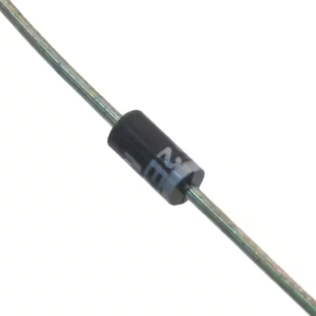
Microchip Technology 1N4744AP/TR12 — Discrete Semiconductors

Microchip 1N4744AP/TR12 Zener Diode, 15 V, 1 W, DO-41

MPN1N4744AP/TR12
Active

Microchip Technology 1N4744AP/TR12 Zener diode, 15 V nominal, 1 W, ±5% tolerance, DO-204AL (DO-41) axial-lead, Tape & Reel.

$1.8150Ref. price · indicative, final on quote
Sourced new & surplus through independent channelsAuthenticity-screened · ESD-safe packingListing updated Aug 2026

Specifications

1N4744AP/TR12 specifications
ParameterValue
MountingThrough Hole
Voltage - zener (Nom)15 V
Voltage - forward (Vf) (Max) @ if1.2 V @ 200 mA
Current - reverse leakage @ vr5 µA @ 11.4 V
Power - max1 W
Operating temperature-65°C~150°C
PackageTape & Reel (TR)
Tolerance±5%
CaseDO-204AL, DO-41, Axial
Impedance (Max)14 Ohms

Product details

15 V Zener — 1 W DO-41 workhorse

The 1N4744AP/TR12 is a 15 V Zener diode in the standard DO-204AL (DO-41) axial-lead package, rated for 1 W continuous power dissipation. The 15 V nominal breakdown voltage with ±5% tolerance puts the actual Zener voltage between 14.25 V and 15.75 V — tight enough for most shunt-regulation and voltage-reference jobs where a 5% band is acceptable. Maximum Zener impedance is 14 Ohms at the test current, which keeps the voltage shift under a few hundred millivolts as the load current varies within the diode's power budget. Reverse leakage is specified at 5 µA max at 11.4 V, so the diode draws negligible current below the knee — useful in battery-powered circuits where the Zener sits across a rail as a clamp.

Package and temperature range

The DO-41 body with 0.025-inch diameter axial leads is a through-hole footprint that hand-solder or wave-solder easily. Forward voltage is 1.2 V max at 200 mA — the diode conducts in the forward direction like a standard rectifier, so it can double as a low-current reverse-polarity protection element if the circuit can tolerate the 1.2 V drop.

Frequently asked questions

What does the ±5% tolerance on the 15 V Zener voltage mean for my circuit?

The ±5% tolerance means the actual Zener voltage at the test current will fall between 14.25 V and 15.75 V. For a shunt regulator or voltage clamp, this band determines the worst-case regulation point — design the series resistor and load current budget around the low end (14.25 V) to ensure the Zener conducts enough current to regulate, and the high end (15.75 V) to stay within the 1 W power limit.