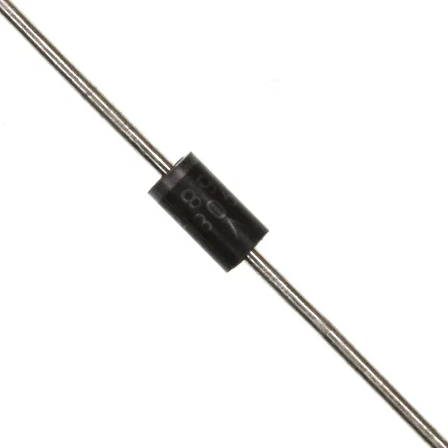
The 1N4744AG/TR: That means the BOM line stays stable for new builds and replacement orders alike, without the sourcing scramble that comes with an obsolete zener.
Zener voltage, tolerance, and power — the fit decisions
The nominal zener voltage is 15 V at ±5 % tolerance, so the actual clamping window sits between 14.25 V and 15.75 V — tight enough to protect a 16 V rail without eating into the operating margin. Rated for 1 W continuous power dissipation in the DO-41 axial package. At 15 V that translates to roughly 66 mA of zener current before hitting the thermal ceiling — a solid guard for low-power shunt regulation or overvoltage clamping on a 12 V bus.
Package and board-fit — DO-41 axial leaded
Supplied in Tape & Reel (TR) for automated insertion, but the part itself is a standard through-hole DO-204AL (DO-41) axial-lead diode. The 0.034-inch lead diameter fits common 0.040-inch plated-through holes on single-layer or double-layer boards.
Additional parametric details for circuit design
Maximum zener impedance (Zzt) is 14 Ohms — a moderate dynamic resistance that keeps the voltage regulation within a few hundred millivolts under varying load current. Reverse leakage is specified at 5 µA maximum with 11.4 V applied across the junction — low enough that it won't drain a battery-backed rail or skew a precision bias network. Forward voltage is 1.2 V maximum at 200 mA forward current — typical for a 1 W silicon diode when conducting in the forward direction.