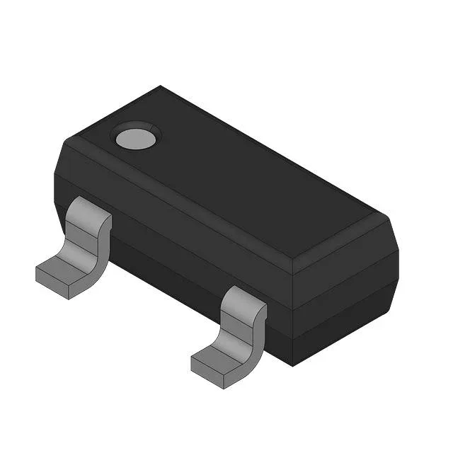
PNP switching transistor for 12 V / 24 V automotive loads
The 200 MHz transition frequency supports switching into the low-MHz range, and the 330 mW power dissipation is adequate for lightly loaded switching stages with proper board-level heat sinking.
60 V Vce and 600 mA Ic — sizing the load switch
The 60 V collector-emitter breakdown covers 12 V and 24 V automotive rails with margin for load-dump transients up to 40 V, though external clamping is still needed for full ISO 7637-2 pulse 5a/b compliance. The 600 mA continuous collector rating sets the steady-state load ceiling; for inductive loads like relays or solenoids, derate to roughly 400 mA to keep the junction below 150°C in a 85°C ambient under the SOT-23 package's thermal resistance. At 500 mA collector current the Vce saturation is 1.6 V maximum with 50 mA base drive — that 1.6 V drop at 500 mA means 800 mW dissipation, which exceeds the 330 mW package limit in continuous operation. For saturated switching above 300 mA, either increase the base drive to lower Vce(sat) or limit the duty cycle to stay within the power budget.
Gain floor for base-drive calculation
The DC current gain (hFE) is guaranteed minimum 100 at 150 mA collector current and 10 V Vce. For a 150 mA load, the base drive needs at least 1.5 mA to guarantee saturation (assuming forced beta of 10). At lower collector voltages (e.g., 1 V to 2 V in deep saturation) the gain drops significantly — the datasheet's typical curves show hFE falling below 50 at Vce = 1 V, so the base drive should be sized for the saturated condition, not the 10 V test point.
The 'T1' suffix indicates a specific lead-frame finish variant (tin-plated), and the 'XT' suffix denotes a bulk-pack option — both are current production codes.