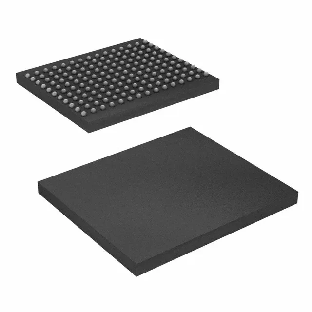
550 MHz QDR II+ SRAM — what this part does on the board
It clocks at 550 MHz and uses a parallel interface, delivering back-to-back read and write operations with no bus-turnaround dead cycles — the defining advantage of QDR II+ over standard synchronous SRAM.
72Mbit at 550 MHz — the throughput decision
The 550 MHz clock rate on a 36-bit-wide QDR II+ bus gives a peak data rate of 39.6 Gbit/s (550 MHz × 36 bits × 2 data transfers per clock, since QDR II+ clocks data on both edges). That bandwidth suits designs that move large lookup tables, packet buffers, or real-time data streams between an FPGA or ASIC and the SRAM. The 2M x 36 organization means the address bus is 21 bits wide, and the data bus is 36 bits — a specific width that matches the native word size of many network processors and FPGAs. If your design uses a narrower bus (e.g., x18 or x9), you will need a different density variant in the same family.
165-ball FBGA — footprint and routing notes
The part comes in a 165-ball LBGA (also specified as 165-FBGA) with a 13x15 mm body. The PCB layout needs via-in-pad or microvia fanout to escape the inner balls, and the 1.7V to 1.9V supply rail requires a dedicated low-noise regulator with adequate decoupling close to the BGA footprint. The supply range (1.7V to 1.9V) is tight — the board must hold that rail within 100 mV under transient load, or the SRAM may lose data integrity at speed.
That restricts this part to controlled indoor environments — server rooms, central offices, lab equipment, and test benches. If the ambient temperature in the system exceeds 70°C, you need a wider-temperature variant (e.g., the -I or -A suffix).
The base product number is CY7C1565, and the full order code includes the speed (550), the package (BZX for FBGA), and the temperature range (C for commercial).